Quick Navigation
Installation
Hardware setup and driver installation
Control Panel
Software configuration and settings
Outputs
Line, headphone, and amplifier outputs
Inputs
Microphone inputs and impedance measurement
Digital I/O
S/PDIF and word clock configuration
GPIO
Auxiliary control connections
API Control
Command-line and API documentation
Download PDF
Printable PDF version
Copyright © 2026 Echo Digital Audio Corporation. All rights reserved.No part of this manual may be reproduced or transmitted in any form or by any means, electronic or mechanical, including photocopying, recording, or by any information storage and retrieval system, without permission in writing from the publisher.Echo Test + Measurement and Echo ATS are trademarks of Echo Digital Audio Corporation. Windows is a trademark of Microsoft Corporation. macOS, Mac, and Macintosh are trademarks of Apple, Inc.
Limited 3 Year Warranty
Limited 3 Year Warranty
Echo warrants its products to be free of manufacturing defects for a period of three years from the date of purchase. Any product covered under a valid Echo new product warranty—where the damage is not caused by owner misuse or abuse (see Warranty Exclusions, below)—will be repaired or replaced by Echo free of charge. Please see the full Echo Warranty Policy for more information.
Regulatory Compliance Information
Regulatory Compliance Information
Echo Digital Audio has conformed and this product conforms, where applicable, to the European Union’s Directive 2002/95/EC on Restrictions of Hazardous Substances (RoHS) as well as the following sections of California law which refer to RoHS, namely sections 25214.10, 25214.10.2, and 58012, Health and Safety Code; Section 42475.2, Public Resources Code.As with the disposal of all old electrical and electronic equipment, this product is not to be treated as regular household waste. Instead, it shall be handed over to the applicable collection point for the recycling of electrical and electronic equipment. CE Compliant
 RoHS
RoHS
 WEEE
WEEE
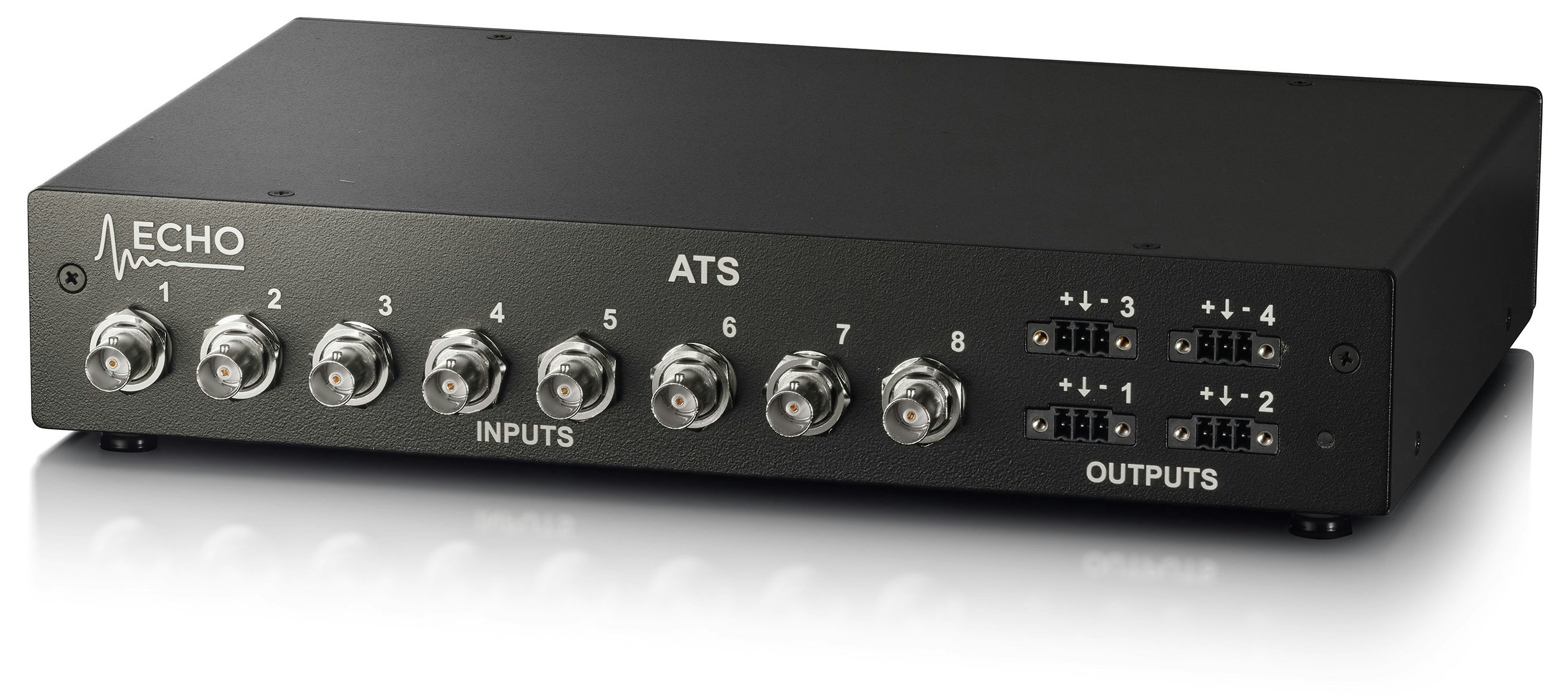
1. Introduction
The Echo ATS Test System is a USB 2.0 compliant audio test platform compatible with ASIO and WASPI drivers on Windows computers, Core Audio on Macintosh (Mac) computers, ALSA on Linux computers. When coupled with a computer running test software, the ATS forms a complete system for testing digital and analog audio electronics and acoustics in consumer and professional products. Echo ATS products are ideally suited for a high-volume production environment where testing occurs on a continual basis. Echo ATS combines the functionality of multiple pieces of test equipment into a single, integrated device for increased reliability at a reduced cost. In addition to audio testing, it has the capability to control measurement fixtures through its GPIO interface.2. Installation
Hardware Setup
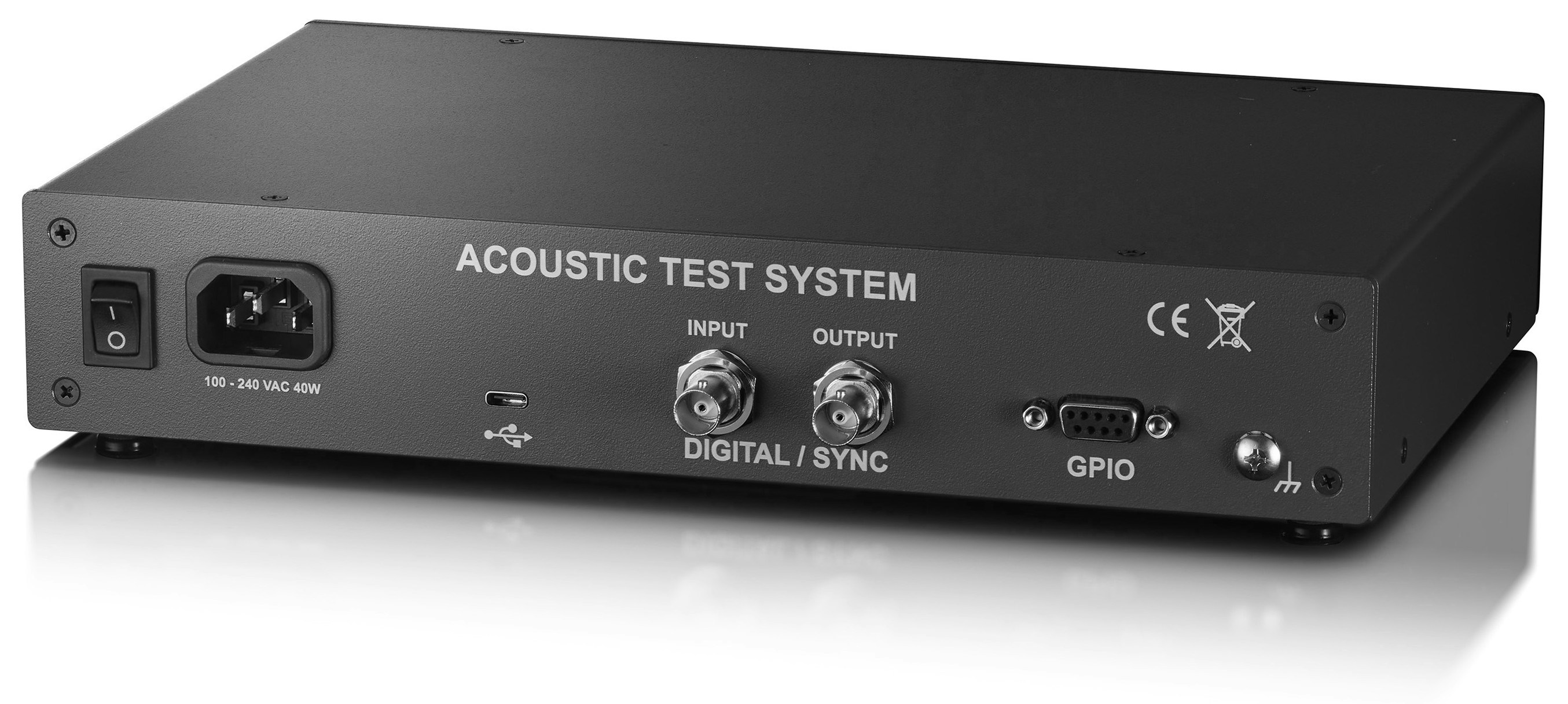
Connect Power
Connect the power cable to the IEC C14 power inlet. Both locking and non-locking cables may be used. The LED on the front panel is green when power is applied and the ATS is operating properly.
The universal AC input accepts 100 – 240 VAC at 50 or 60 Hz. The ATS, equipment connected to the ATS, and the test computer must all be connected to the same surge-protected power strip.
Driver Installation
- Windows
- macOS
Windows Driver Installation
Download the ATS Windows driver and run the installer.The installer includes:- ATS Control Panel application
- Latest firmware updates
- ASIO driver (appears as “ASIO Echo ATS”)
- Command-line utilities
Although Windows 10/11 will automatically recognize the ATS using the built-in WASAPI driver, we strongly recommend installing the Echo software for:
- Control panel functionality
- Firmware update capability
- ASIO driver support (required by most professional audio applications)
3rd Party Test and Measurement Software
The Echo ATS Test System may be used with a wide variety of 3rd party test and measurement software via the Echo ATS ASIO driver. Because ASIO is a digital interface, all levels are communicated between the hardware and software as digital values, and there’s no inherent conversion to actual analog I/O values when using an analog interface. To properly do the conversion, the software needs to know the correct scaling factor, which defines the relationship between analog voltage and digital full-scale level (0 dBFS). The scaling factors for different types of inputs and outputs are typically different. For example, the scaling factor of a line-level output will be different than for a speaker output, because the maximum voltage of a speaker output is greater. Although scaling factors can be determined by experimentation using a calibrated voltage meter, we provide you with the correct scaling factors for our hardware. You can simply enter these values into the appropriate settings in the measurement software that you are using.Scaling Factors Reference
- Output Scaling
- Input Scaling
| IO Type | Scaling Factor |
|---|---|
| Line (unbalanced) | 4.0 V/FS |
| Line (balanced) | 8.0 V/FS |
| Headphone | 3.0 V/FS |
| Amplifier/Speaker | 9.545 V/FS |
3. ATS Control Panel
Overview
The control panel controls and monitors the following ATS hardware functions:- Analog input and output gain
- Constant-current power to microphones
- TEDS data
- Level meters
- Firmware update
- WASAPI and ASIO driver settings
- Clock source and status
- Diagnostic logging and directory
Channels Tab
The Echo Acoustic Test System Inputs and Outputs are configurable for testing different types of devices (i.e., acoustic, line level, headphone, or speaker). When you configure ATS I/O for testing different types of devices, it adjusts the relative voltage and phase based on the desired setup.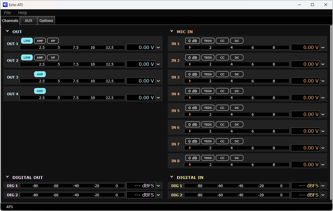
Figure 3: Channels tab (ATS-SH)
4. Analog Outputs
Overview
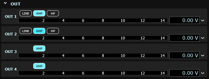
The ATS provides four configurable analog output channels with three distinct operating modes optimized for different test scenarios. Channels 1 and 2 are fully configurable between all three modes, while channels 3 and 4 are dedicated amplifier outputs.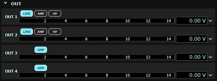
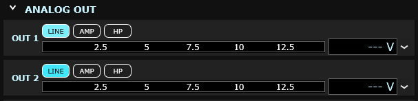
Output Configuration
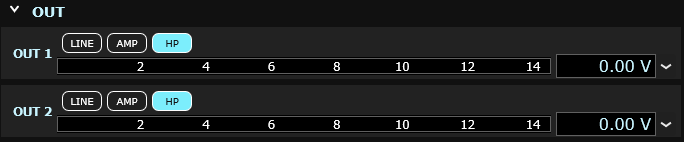
The output level of each channel is displayed both on a horizontal bar graph and numerically. Use the drop-down control to select the desired units (dBFS, percentage, or voltage).Mode Selection: On Channels 1 and 2, click LINE, AMP, or HP to change the output mode. Changing the output mode adjusts the relative voltage and phase of the output port.
Output Mode Specifications
| Mode | Configuration | DC Offset | Max Output | Ground Connection |
|---|---|---|---|---|
| AMP | Floating differential | 7.5V | 12.4Vpp | Do NOT Connect |
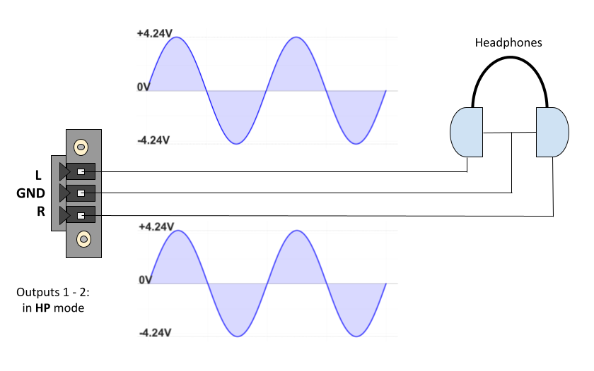
| HP | Single-ended | 0V | 8.5Vpp | Required (shared) |
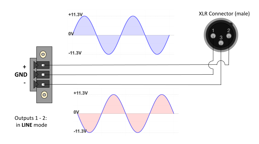
| LINE | Balanced | 0V | 22.6Vpp | Optional |
Output Modes
- Amplifier (AMP)
- Headphone (HP)
- Line Level (LINE)
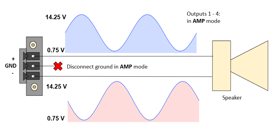
Amplifier/Speaker Outputs
The AMP mode is designed for making acoustic measurements of speakers, drivers, and other acoustic transducers. This mode provides floating differential outputs with sufficient power to drive speakers directly.Applications
Applications
- Speaker and driver testing
- Measurement microphones
- Ear simulators and artificial heads
- Actuators and mouth simulators
Technical Specifications
Technical Specifications
- Configuration: Floating differential
- DC Bias: 7.5V on both (+) and (-) terminals
- Maximum Output: 27.0 Vpp
- Available on: Channels 1-4 (Channels 3-4 are AMP only)y
5. Analog Inputs
Microphone / Line Inputs
Inputs with BNC connectors are available for connecting externally polarized or prepolarized constant current (CCP/IEPE/ICP, 4 mA) microphones, or unbalanced line-level inputs. Input gain control, constant current supply, DC coupling, and TEDS reading are available at each input and are under software control via the ATS control panel. The mic/line inputs are designed to accommodate a very wide range of input voltages, from extremely low-level dynamic microphones all the way to line level inputs. To cover such a wide range of voltages, five input gain levels (+0 db, +10 db, +20 db, +30 db, +40 db) are available. The gain settings are individually adjustable for each channel. Keep in mind that setting the input gain higher will also amplify the noise floor, so the best practice is to use the lowest gain setting needed for a particular application. This will result in the best dynamic range for the measurements.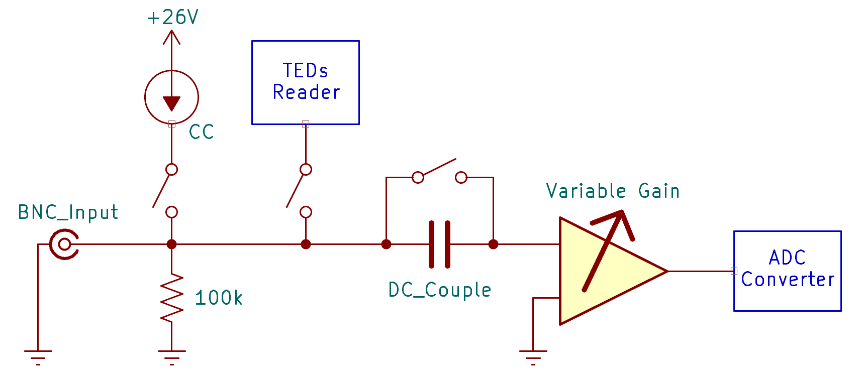
Figure 14: Simplified Circuit Diagram of a single Input Channel
Inputs Channel Tab
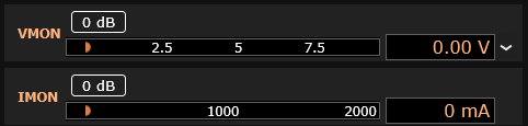
Input channels are similarly shown on the right side of the Channels tab. The input level of each channel is displayed both on a horizontal bar graph and numerically. Use the drop-down control to select the desired units. Mic/line inputs contain the following additional controls: Gain: Sets gain to +0 db, +10 db, +20 db, +30 db or +40 db to accommodate a wide range of signal levels. TEDS: Displays the TEDS (Transducer Electronic Data Sheet) information reported back from the attached microphone, if the microphone supports it. See the TEDS section below for more details. CC: Toggle the constant current supply (CCP/IEPE/ICP) to power prepolarized measurement microphones. DC: Toggle DC coupling Click the caret to expand or condense the channel display for each module type. In the condensed view, only the bar-graphs are visible.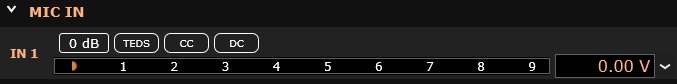
Figure 15: Analog Input channel
6. Digital IO
The ATS includes SPDIF digital audio input and output on BNC connectors located on the rear panel. The system provides two input channels and two output channels that can operate simultaneously with the analog I/O.Specifications
The digital interface uses consumer SPDIF format (IEC60958) with 24-bit resolution and supports standard sample rates from 44.1 kHz to 192 kHz. The SPDIF signal is self-clocking, extracting timing from the digital stream itself. Digital channels map to the ASIO driver as:- Input: Channels 9 and 10
- Output: Channels 5 and 6
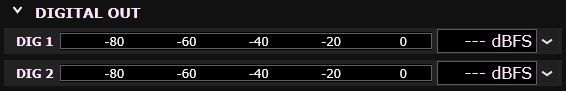
Digital I/O Meters
In the Channels tab, the Digital In and Digital Out sections show real-time levels for channels Dig 1 and Dig 2. Levels display in either dBFS or percentage.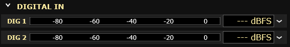
- SPDIF Mode: Standard digital audio operation
- Word Clock Mode: Synchronization input/output
Options Tab
The Options tab contains information about the connected ATS test system and allows various configuration options to be set. Its controls and indicators are described below.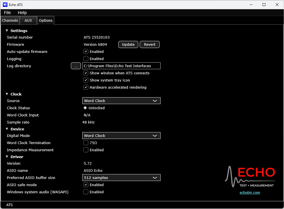
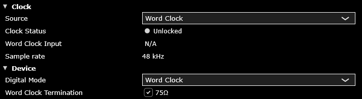
Figure 4: Options tab
Word Clock Mode
When selected from the Digital IO dropdown, the ATS configures the digital I/O BNC connectors for word clock operation. The clock can either be received from an external source (Word Clock) or generated by the ATS (Internal) for synchronizing multiple audio devices. When in Word Clock mode, the SPDIF input and output channels are disabled.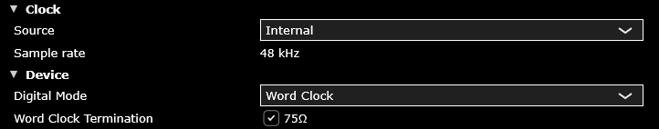
Device
- Serial Number: Unique serial number for the device. This can also be found on the bottom of the unit.
- Firmware: Displays the current firmware version and allows you to manually update or revert to the factory supplied version.
- Auto-update firmware: When checked, you will be prompted to update the firmware if the control panel includes a later version than is already installed.
- Logging: Enables diagnostic logging. You typically do not need to enable logging unless requested by Echo support.
- Log directory: Directory where the log file will be stored.
Clock
- Source: Selects the clock source as Internal (the ATS’s built-in crystal oscillator).
- Sample rate: Shows the ASIO clock rate selected in the measurement software.
Control Panel
- Show window when ATS connects: Shows the control panel window when the ATS test system is connected.
- Show system tray icon: Shows the control panel icon in the system tray when running.
- GPU accelerated rendering: When checked, allows the GPU (graphics card) to offload from the CPU the task of redrawing of the control panel meters.
Driver
- Version: Currently installed driver version.
- ASIO name: Shows the name of the Echo ASIO driver as it will be displayed in the measurement software.
- Windows system audio (WASPI): Enables the Windows WASAPI audio driver. Leave this unchecked unless you are running software that only supports WASAPI and does not support ASIO.
File Menu
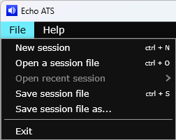
Figure 5: File menu
The File menu allows you to open and save sessions. An ATS session stores all the current hardware settings in a text file that can be used to reset the hardware to a previous state.
Additionally, the ATS command-line application can read session files, so you can fully configure the ATS, save the configuration as a session, and then later load all those settings using a single command-line call.
It is not usually necessary to directly edit the session file, as the easiest way to construct it is simply to set the control panel up as desired and then save the session. It can be, however, be easily edited in a text editor.
TEDS
When the TEDS button is clicked, the TEDS data window will be displayed. If the attached microphone does not support TEDS, then a message “TEDS device not found” will be shown instead of the data.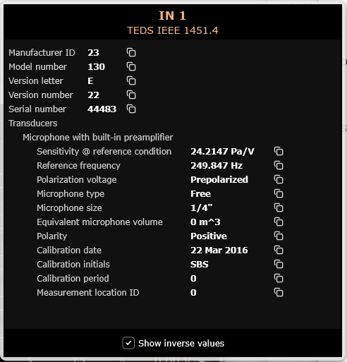
Figure 16: TEDS data window
TEDS data is not automatically transferred to the audio analysis software—it must be copied and pasted or manually entered into the appropriate field(s). Data may easily be copied by clicking the icon to the right of each line.
Sensitivity is displayed by default in units of Volt/Pascal. Some audio test software, such as Audio Precision’s APx500 Flex, requires the sensitivity data to be entered in units of Pascals/Volt (also called the “scaling factor”). Checking the “Show inverse units” checkbox at the bottom will switch the “Sensitivity @ reference condition” units to Pascals/Volt.
Impedance Measurement
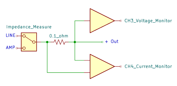
The ATS provides real-time impedance measurement capability for characterizing speakers, headphones, drivers, and other loads across different frequencies. This feature works in either LINE and AMP output modes using Output 1.How It Works
The impedance measurement system uses a four-wire (Kelvin) measurement technique:The current sense resistor is permanently connected in series with the positive (+) terminal of Output 1 and is not externally accessible.
Configuration
Connect DUT
Connect your device under test to Output 1 using the three-pin connector (+, -, and ground as needed)
Enable Impedance Mode
In the Device section, click the Impedance Enable checkbox to activate impedance measurement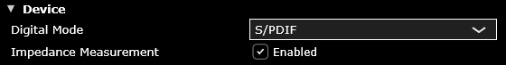
Limitations: Impedance measurement is currently available only on Output 1. When not in impedance mode, Inputs 3 and 4 function as standard Mic/Line inputs.
Aux (GPIO)
The ATS features 4 TTL level inputs and 4 open drain TTL level outputs capable of sinking up to 250mA of current on a female 9 pin locking D-sub connector. They allow sending and receiving switch closure information under program control for interfacing to other test or display devices. A simple application of this feature would be to illuminate a Pass/Fail light-bar based on test results. Navigate to the Aux tab in the control panel to monitor and control the auxiliary inputs and outputs.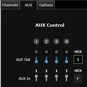
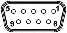
Table 3 DB9 Connector Pinout
| Function | Pin |
|---|---|
| Aux Out 1 | 7 |
| Aux Out 2 | 2 |
| Aux Out 3 | 6 |
| Aux Out 4 | 1 |
| Aux In 1 | 5 |
| Aux In 2 | 9 |
| Aux In 3 | 4 |
| Aux In 4 | 8 |
| Ground | 3 |
Contact Echo for info or support.