> ## Documentation Index
> Fetch the complete documentation index at: https://support.echotm.com/llms.txt
> Use this file to discover all available pages before exploring further.
# AP Flex Setup Guide
> Step-by-step guide for configuring APx500 Flex to work with the Echo ATS and running a basic acoustic test
## Prerequisites
Before starting, ensure the following are in place:
* **Echo ATS** powered on and connected to your computer via USB
* **Echo ATS Windows driver** installed (includes the ASIO driver). See [Downloads](/ats/downloads)
* **APx500 Flex** installed on the same computer
* A measurement microphone connected to an ATS mic/line input
* A speaker or driver connected to an ATS amplifier output
The ATS ASIO driver name appears as **"ASIO Echo"** in APx500 Flex. If you do not see it, verify the Echo ATS driver is installed from the [Downloads](/ats/downloads) page.
## Setting Up the ASIO Connection
Under **Signal Path Setup** in APx500 Flex for **Output** and **Input** connector settings, set the connection type to **ASIO**.
From the ASIO device dropdown, select **ASIO Echo**.
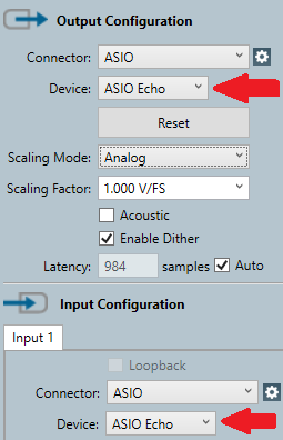 If "ASIO Echo ATS" does not appear in the device list, confirm that the ATS is powered on, connected via USB, and that the Echo driver is installed. You may need to restart AP Flex after installing the driver.
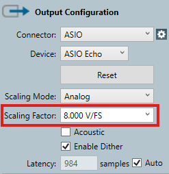
Set the scaling mode to **Analog** for both the output and input. Without the correct scaling, AP Flex cannot accurately convert between digital values and real-world voltage or SPL measurements.
Enter the appropriate output scaling factor based on the output mode you are using on the ATS:
| Output Mode | Scaling Factor |
| :---------------- | :------------- |
| Line (unbalanced) | 4.0 V/FS |
| Line (balanced) | 8.0 V/FS |
| Headphone | 3.0 V/FS |
| Amplifier/Speaker | 9.545 V/FS |
If "ASIO Echo ATS" does not appear in the device list, confirm that the ATS is powered on, connected via USB, and that the Echo driver is installed. You may need to restart AP Flex after installing the driver.
Set the scaling mode to **Analog** for both the output and input. Without the correct scaling, AP Flex cannot accurately convert between digital values and real-world voltage or SPL measurements.
Enter the appropriate output scaling factor based on the output mode you are using on the ATS:
| Output Mode | Scaling Factor |
| :---------------- | :------------- |
| Line (unbalanced) | 4.0 V/FS |
| Line (balanced) | 8.0 V/FS |
| Headphone | 3.0 V/FS |
| Amplifier/Speaker | 9.545 V/FS |
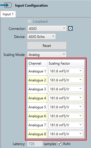
 Enter the appropriate input scaling factor for the ATS input you are using:
| Input Type | Scaling Factor | |
| :------------- | :------------- | ----------- |
| Mic-Line | 161.6 mFS/V | |
| Impedance VMON | 80.80 mFS/V | |
| Impedance IMON | 161.6 mFS/V | (1mV = 1mA) |
Enter the appropriate input scaling factor for the ATS input you are using:
| Input Type | Scaling Factor | |
| :------------- | :------------- | ----------- |
| Mic-Line | 161.6 mFS/V | |
| Impedance VMON | 80.80 mFS/V | |
| Impedance IMON | 161.6 mFS/V | (1mV = 1mA) |
 If your microphone has TEDS data, you can read the sensitivity from the ATS Control Panel's TEDS window. Check "Show inverse units" to display sensitivity in Pascals/Volt, which is the format AP Flex expects. See the [ATS User Manual](/ats/ats-user-manual#teds) for details.
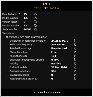 The microphone sensitivity can also be measured using a multifunction sound calibrator.
Enter the microphone sensitivity in AP Flex under **Signal Path Setup** for the input channel. This allows AP Flex to convert the measured voltage back into sound pressure level (SPL) for accurate acoustic measurements.
The microphone sensitivity can also be measured using a multifunction sound calibrator.
Enter the microphone sensitivity in AP Flex under **Signal Path Setup** for the input channel. This allows AP Flex to convert the measured voltage back into sound pressure level (SPL) for accurate acoustic measurements.
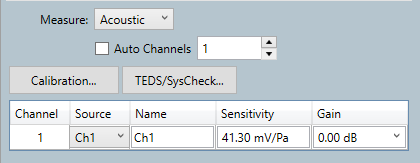 In this example we are only using one microphone input. So we unchecked 'Auto channels' and set the number of channels to 1.
## Running a Basic Acoustic Test
With the signal path configured, you can run a basic acoustic measurement to verify the setup and characterize your speaker-microphone system.
### Hardware Setup
Open the **ATS Control Panel** and set the output channel connected to your speaker to **AMP** mode. This configures the output as a floating differential amplifier output suitable for driving speakers directly.
In this example we are only using one microphone input. So we unchecked 'Auto channels' and set the number of channels to 1.
## Running a Basic Acoustic Test
With the signal path configured, you can run a basic acoustic measurement to verify the setup and characterize your speaker-microphone system.
### Hardware Setup
Open the **ATS Control Panel** and set the output channel connected to your speaker to **AMP** mode. This configures the output as a floating differential amplifier output suitable for driving speakers directly.
 Amplifier outputs are floating and not ground-referenced. Do **not** connect the ground terminal when using AMP mode. Connect the speaker across the + and - terminals only.
In the ATS Control Panel, configure the input channel connected to your microphone:
* **Gain:** Set to the appropriate level for your microphone. Start with +0 dB and increase if needed. Use the lowest gain setting that provides sufficient signal level for the best dynamic range.
* **CC (Constant Current):** Enable if using a CCP/IEPE/ICP powered measurement microphone.
Amplifier outputs are floating and not ground-referenced. Do **not** connect the ground terminal when using AMP mode. Connect the speaker across the + and - terminals only.
In the ATS Control Panel, configure the input channel connected to your microphone:
* **Gain:** Set to the appropriate level for your microphone. Start with +0 dB and increase if needed. Use the lowest gain setting that provides sufficient signal level for the best dynamic range.
* **CC (Constant Current):** Enable if using a CCP/IEPE/ICP powered measurement microphone.
 Place the measurement microphone at the desired test position relative to the speaker. For a basic frequency response measurement, position the microphone on-axis with the speaker at a consistent, known distance.
### Running the Measurement
In APx500 Flex under the Navigator, click the 'Add Measurement' button and select an acoustic measurement such as **Frequency Response** or **THD+N**. These measurements will use the signal path you configured above.
Place the measurement microphone at the desired test position relative to the speaker. For a basic frequency response measurement, position the microphone on-axis with the speaker at a consistent, known distance.
### Running the Measurement
In APx500 Flex under the Navigator, click the 'Add Measurement' button and select an acoustic measurement such as **Frequency Response** or **THD+N**. These measurements will use the signal path you configured above.
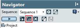
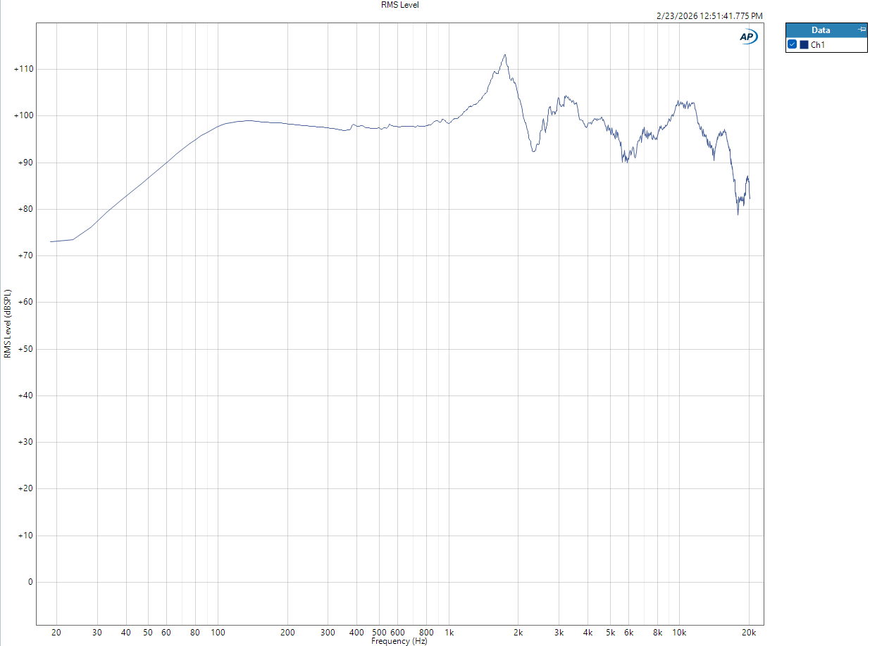
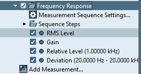 Click the **Run** button to execute the measurement. AP Flex will generate the stimulus signal through the ATS amplifier output, and capture the microphone response through the ATS input. Results will be displayed in the AP Flex measurement graphs.
 Check that the measurement results are reasonable:
* Signal levels should be well above the noise floor
* No clipping should be visible on either the output or input (check the ATS Control Panel meters)
* The frequency response shape should be consistent with the expected behavior of your speaker and microphone
Check that the measurement results are reasonable:
* Signal levels should be well above the noise floor
* No clipping should be visible on either the output or input (check the ATS Control Panel meters)
* The frequency response shape should be consistent with the expected behavior of your speaker and microphone
 ## Troubleshooting
Verify that the ATS is powered on and connected via USB. Confirm the Echo ATS driver is installed by checking that the ATS Control Panel opens. Restart AP Flex after connecting the ATS.
* Confirm the microphone is connected to the correct BNC input
* Check that constant current (CC) is enabled in the ATS Control Panel if your microphone requires it
* Try increasing the input gain setting
* Verify the correct input channel is assigned in AP Flex
Contact Echo for info or support.
## Troubleshooting
Verify that the ATS is powered on and connected via USB. Confirm the Echo ATS driver is installed by checking that the ATS Control Panel opens. Restart AP Flex after connecting the ATS.
* Confirm the microphone is connected to the correct BNC input
* Check that constant current (CC) is enabled in the ATS Control Panel if your microphone requires it
* Try increasing the input gain setting
* Verify the correct input channel is assigned in AP Flex
Contact Echo for info or support.