> ## Documentation Index
> Fetch the complete documentation index at: https://support.echotm.com/llms.txt
> Use this file to discover all available pages before exploring further.
# AIO User Manual
> Complete guide for installation, configuration, and operation of the Echo AIO All-in-One Test System
 ## Quick Navigation
Hardware setup and driver installation
Module types and combinations
Detailed module specifications
Input and output specifications
TDM interface configuration
Software configuration interface
Command-line and API documentation
Complete technical specifications
**Copyright © 2023 Echo Digital Audio Corporation. All rights reserved.**
No part of this manual may be reproduced or transmitted in any form or by any means, electronic or mechanical, including photocopying, recording, or by any information storage and retrieval system, without permission in writing from the publisher.
Echo Test + Measurement and Echo AIO are registered trademarks of Echo Digital Audio Corporation. Windows is a trademark of Microsoft Corporation. macOS, Mac, and Macintosh are trademarks of Apple, Inc.
**Revision 3, June 20, 2023**
Echo Test + Measurement
402 E Carrillo St Ste A, Santa Barbara CA 93101 USA
echotm.com | [sales@echotm.com](mailto:sales@echotm.com) | +1 805-880-5590
Echo warrants its products to be free of manufacturing defects for a period of three years from the date of purchase. Any product covered under a valid Echo new product warranty—where the damage is not caused by owner misuse or abuse (see Warranty Exclusions, below)—will be repaired or replaced by Echo free of charge. **Please see the full Echo Warranty Policy for more information.**
**CE Compliant** - This product meets European Union safety and electromagnetic compatibility requirements.
**RoHS Notice:** Echo Digital Audio has conformed and this product conforms, where applicable, to the European Union's Directive 2002/95/EC on Restrictions of Hazardous Substances (RoHS) as well as the following sections of California law which refer to RoHS, namely sections 25214.10, 25214.10.2, and 58012, Health and Safety Code; Section 42475.2, Public Resources Code.
**WEEE:** As with the disposal of all old electrical and electronic equipment, this product is not to be treated as regular household waste. Instead, it shall be handed over to the applicable collection point for the recycling of electrical and electronic equipment.
## Quick Navigation
Hardware setup and driver installation
Module types and combinations
Detailed module specifications
Input and output specifications
TDM interface configuration
Software configuration interface
Command-line and API documentation
Complete technical specifications
**Copyright © 2023 Echo Digital Audio Corporation. All rights reserved.**
No part of this manual may be reproduced or transmitted in any form or by any means, electronic or mechanical, including photocopying, recording, or by any information storage and retrieval system, without permission in writing from the publisher.
Echo Test + Measurement and Echo AIO are registered trademarks of Echo Digital Audio Corporation. Windows is a trademark of Microsoft Corporation. macOS, Mac, and Macintosh are trademarks of Apple, Inc.
**Revision 3, June 20, 2023**
Echo Test + Measurement
402 E Carrillo St Ste A, Santa Barbara CA 93101 USA
echotm.com | [sales@echotm.com](mailto:sales@echotm.com) | +1 805-880-5590
Echo warrants its products to be free of manufacturing defects for a period of three years from the date of purchase. Any product covered under a valid Echo new product warranty—where the damage is not caused by owner misuse or abuse (see Warranty Exclusions, below)—will be repaired or replaced by Echo free of charge. **Please see the full Echo Warranty Policy for more information.**
**CE Compliant** - This product meets European Union safety and electromagnetic compatibility requirements.
**RoHS Notice:** Echo Digital Audio has conformed and this product conforms, where applicable, to the European Union's Directive 2002/95/EC on Restrictions of Hazardous Substances (RoHS) as well as the following sections of California law which refer to RoHS, namely sections 25214.10, 25214.10.2, and 58012, Health and Safety Code; Section 42475.2, Public Resources Code.
**WEEE:** As with the disposal of all old electrical and electronic equipment, this product is not to be treated as regular household waste. Instead, it shall be handed over to the applicable collection point for the recycling of electrical and electronic equipment.
 **CE Compliant**
 **RoHS**
 **WEEE**
## Safety Instructions
1. **Read Instructions** — Be sure to read all the safety and operating instructions before operating this product.
2. **Keep Instructions** — The safety instructions and user manual should be kept for future reference.
3. **Warnings** — All warnings on your Echo AIO and in the user manual should be followed.
4. **Follow Instructions** — All operating and use instructions should be followed.
5. **Moisture** — Water and moisture are detrimental to proper operation. Do not install or operate near sources of water or moisture.
6. **Heat** — Your Echo AIO should be situated away from sources of heat such as heaters or radiators.
7. **Power Sources** — Operate only from stable AC power as indicated. Use a surge protector in areas subject to lightning or industrial noise.
8. **Grounding** — Do not undermine grounding capabilities. Use the provided grounded plug in a properly grounded outlet.
9. **Power Cord Protection** — Route power cords to protect them from damage, particularly at plugs, outlets, and exit points.
10. **Servicing** — No user serviceable parts inside. Do not attempt service yourself. Refer all servicing to qualified personnel.
**NOTE: There are no user serviceable parts inside. Do not attempt to remove modules from the chassis. Doing so will void the warranty and calibration!**
# 1. Introduction
The Echo AIO Test System is a USB 2.0 compliant audio test platform compatible with ASIO and WASAPI drivers on Windows computers and Core Audio on Macintosh (Mac) computers. When coupled with a computer running test software, AIO forms a complete system for testing digital and analog audio electronics and acoustics in consumer and professional products. Echo AIO products are ideally suited for a high-volume production environment where testing occurs on a continual basis.
Echo AIO combines the functionality of multiple pieces of test equipment into a single, integrated device for increased reliability at a reduced cost. In addition to audio testing, it has extensive capability to control measurement fixtures, simulate batteries for wearable products, and even measure environmental variables such as temperature, barometric pressure, and humidity, allowing baseline conditions to be established for factory production runs.
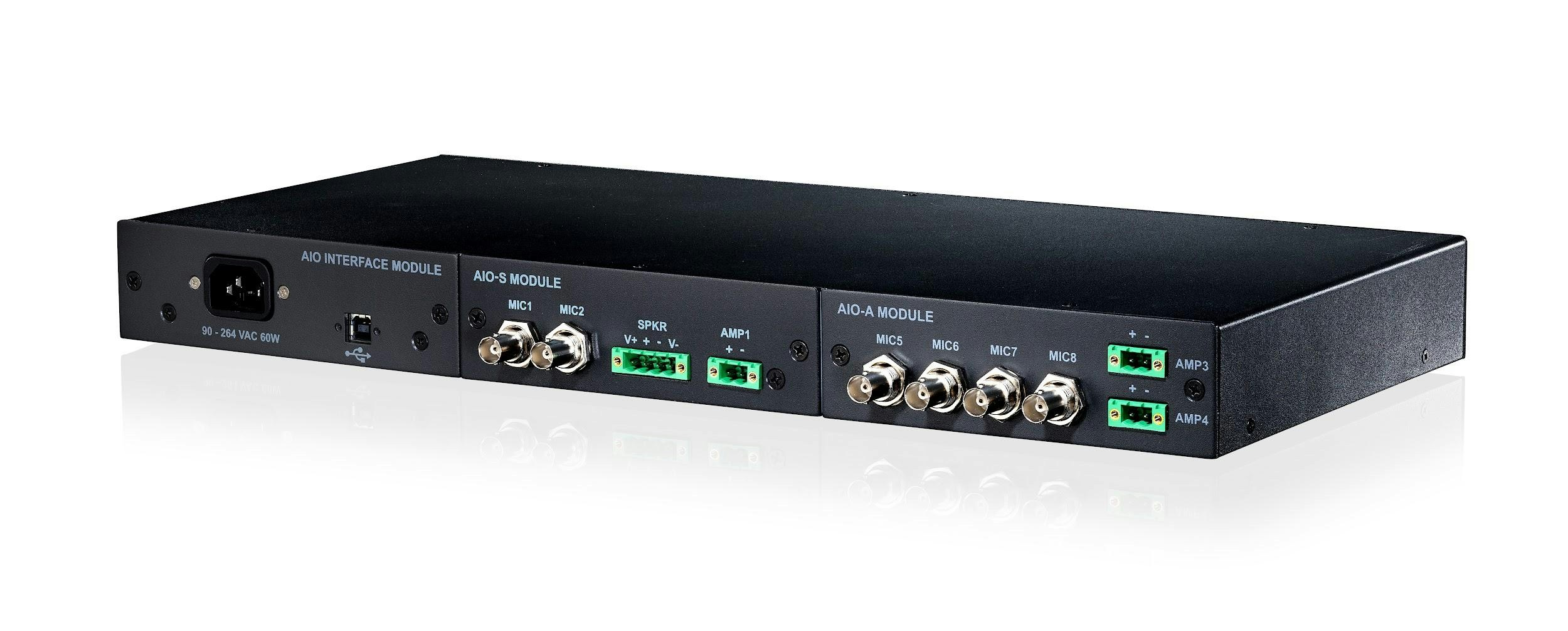
*Figure 1: Echo AIO Test System (AIO-SA configuration)*
The Echo AIO Test System is a modular design consisting of a chassis, an interface module with connections for a locking USB 2.0 cable and a locking power cable, and one or two modules selected from a variety of types for analog I/O, digital I/O, or control. The product name is based on the combination of installed modules (i.e.: AIO-SA has one AIO-S and one AIO-A module).
**WEEE**
## Safety Instructions
1. **Read Instructions** — Be sure to read all the safety and operating instructions before operating this product.
2. **Keep Instructions** — The safety instructions and user manual should be kept for future reference.
3. **Warnings** — All warnings on your Echo AIO and in the user manual should be followed.
4. **Follow Instructions** — All operating and use instructions should be followed.
5. **Moisture** — Water and moisture are detrimental to proper operation. Do not install or operate near sources of water or moisture.
6. **Heat** — Your Echo AIO should be situated away from sources of heat such as heaters or radiators.
7. **Power Sources** — Operate only from stable AC power as indicated. Use a surge protector in areas subject to lightning or industrial noise.
8. **Grounding** — Do not undermine grounding capabilities. Use the provided grounded plug in a properly grounded outlet.
9. **Power Cord Protection** — Route power cords to protect them from damage, particularly at plugs, outlets, and exit points.
10. **Servicing** — No user serviceable parts inside. Do not attempt service yourself. Refer all servicing to qualified personnel.
**NOTE: There are no user serviceable parts inside. Do not attempt to remove modules from the chassis. Doing so will void the warranty and calibration!**
# 1. Introduction
The Echo AIO Test System is a USB 2.0 compliant audio test platform compatible with ASIO and WASAPI drivers on Windows computers and Core Audio on Macintosh (Mac) computers. When coupled with a computer running test software, AIO forms a complete system for testing digital and analog audio electronics and acoustics in consumer and professional products. Echo AIO products are ideally suited for a high-volume production environment where testing occurs on a continual basis.
Echo AIO combines the functionality of multiple pieces of test equipment into a single, integrated device for increased reliability at a reduced cost. In addition to audio testing, it has extensive capability to control measurement fixtures, simulate batteries for wearable products, and even measure environmental variables such as temperature, barometric pressure, and humidity, allowing baseline conditions to be established for factory production runs.
*Figure 1: Echo AIO Test System (AIO-SA configuration)*
The Echo AIO Test System is a modular design consisting of a chassis, an interface module with connections for a locking USB 2.0 cable and a locking power cable, and one or two modules selected from a variety of types for analog I/O, digital I/O, or control. The product name is based on the combination of installed modules (i.e.: AIO-SA has one AIO-S and one AIO-A module).
 *Figure 2: AIO's modular interface*
All Echo AIO products come from the factory in predetermined, fixed configurations. Attempting to change the factory configuration or swapping modules between chassis will cause the AIO to stop working properly and will **void the calibration and the warranty!** Products originally configured with a single module and an empty slot may be returned to a factory authorized service station at a later date to add a second module.
# 2. Installation
## Hardware
Connect the locking power cable supplied with the AIO to the locking IEC C14 power inlet. Both locking and non-locking cables may be used. For reliability, the AIO does not have a power switch. The blue LED on the front panel indicates when power is applied and the AIO is operating.
*Figure 2: AIO's modular interface*
All Echo AIO products come from the factory in predetermined, fixed configurations. Attempting to change the factory configuration or swapping modules between chassis will cause the AIO to stop working properly and will **void the calibration and the warranty!** Products originally configured with a single module and an empty slot may be returned to a factory authorized service station at a later date to add a second module.
# 2. Installation
## Hardware
Connect the locking power cable supplied with the AIO to the locking IEC C14 power inlet. Both locking and non-locking cables may be used. For reliability, the AIO does not have a power switch. The blue LED on the front panel indicates when power is applied and the AIO is operating.
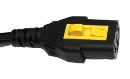 *Figure 3: Locking power cable*
The universal AC input accepts 90 – 264 VAC at 50 or 60 Hz. The AIO, equipment connected to the AIO, and the test computer must all be connected to the same surge-protected power strip.
Connect the Type-B end of the supplied locking USB 2.0 "HI-SPEED" cable to the USB connector on the AIO, and the other end to the host computer. Both locking and non-locking cables may be used.
*Figure 3: Locking power cable*
The universal AC input accepts 90 – 264 VAC at 50 or 60 Hz. The AIO, equipment connected to the AIO, and the test computer must all be connected to the same surge-protected power strip.
Connect the Type-B end of the supplied locking USB 2.0 "HI-SPEED" cable to the USB connector on the AIO, and the other end to the host computer. Both locking and non-locking cables may be used.
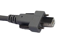 *Figure 4: Locking USB cable*
## Echo Driver Software
### Windows Installation
Download the AIO Windows driver from the downloads section of the Echo website and run the installer. This will install:
* AIO control panel
* Latest firmware
* ASIO driver
* Command-line application
Although the AIO will automatically be recognized on Windows 10 or 11 and can function using only Windows' built-in WASAPI driver, we recommend installing the Echo software to add control panel functionality, firmware updates, and ASIO driver support. Most professional audio and test applications support ASIO. The driver will appear in your software as "ASIO Echo AIO".
### macOS Installation
For Macintosh computers, support for USB audio is part of the macOS and its audio component, Core Audio. The AIO is automatically detected whenever it is powered on and connected to a Mac USB port.
## 3rd Party Test and Measurement Software
The Echo AIO Test System may be used with a wide variety of 3rd party test and measurement software via the Echo AIO ASIO driver. Because ASIO is a digital interface, all levels are communicated between the hardware and software as digital values, and there's no inherent conversion to actual analog I/O values when using an analog interface.
To properly do the conversion, the software needs to know the correct scaling factor, which defines the relationship between analog voltage and digital full-scale level (0 dBFS). The scaling factors for different types of inputs and outputs are typically different.
### Scaling Factors
| Type | Connector | Module | Scaling Factor |
| ----------- | :------------------------: | :---------------: | :------------: |
| **Outputs** | | | |
| | Line (unbalanced) | AIO-L | 8.0 V/FS |
| | Line (balanced) | AIO-L | 16.0 V/FS |
| | Headphone | AIO-H | 3.0 V/FS |
| | Amplifier/Speaker | AIO-A, -S | 9.545 V/FS |
| **Inputs** | | | |
| | Mic-Line | AIO-A, -H, -L, -S | 161.6 mFS/V |
| | Headphone Impedance VMON | AIO-H | 333.3 mFS/V |
| | Headphone Impedance IMON\* | AIO-H | 8.0 FS/V |
| | Speaker Impedance VMON | AIO-S | 80.80 mFS/V |
| | Speaker Impedance IMON\* | AIO-S | 161.6 mFS/V |
\*Current monitor inputs require special calculation to derive impedance values
# 3. Hardware Configurations
The Echo AIO Test System is available in different hardware configurations (models) depending on the module type and position installed in the chassis. The product name is based on the combination of installed modules (i.e.: AIO-SA has one AIO-S and one AIO-A module).
### Common AIO Configurations
| Model.... | Inner Module | Outer Module | Mic/Line Inputs | Line Outputs | HP Outputs | Amp Outputs | Impedance |
| :--------: | :----------: | :----------: | :-------------: | :----------: | :--------: | :---------: | :-------: |
| **AIO-A1** | AIO-A | - | 4 | - | - | 2 | - |
| **AIO-A2** | AIO-A | AIO-A | 8 | - | - | 4 | - |
| **AIO-AH** | AIO-A | AIO-H | 6 | - | 2 | 2 | 1 |
| **AIO-H1** | AIO-H | - | 2 | - | 2 | - | 1 |
| **AIO-H2** | AIO-H | AIO-H | 4 | - | 4 | - | 2 |
| **AIO-L1** | AIO-L | - | 4 | 2 | - | - | - |
| **AIO-L2** | AIO-L | AIO-L | 8 | 4 | - | - | - |
| **AIO-S1** | AIO-S | - | 2 | - | - | 2 | 1 |
| **AIO-S2** | AIO-S | AIO-S | 4 | - | - | 4 | 2 |
| **AIO-SA** | AIO-S | AIO-A | 6 | - | - | 3 | 1 |
| **AIO-SL** | AIO-S | AIO-L | 6 | 2 | - | 2 | 1 |
Additional configurations are possible, as long as they follow these rules:
a. Any combination of two analog audio modules (A, H, L or S) may be ordered, with either module in the inner or outer slot.
b. Any analog audio module (A, H, L or S) may be ordered for the inner slot, along with a T module in the outer slot.
c. For a single-module unit, the analog modules (A, H, L, or S) may be placed in either slot.
Modules are not sold separately, except as part of an upgrade by an authorized dealer to convert a single-module chassis to a two-module chassis. Modules do not function as stand-alone devices. They must be installed in an AIO chassis to operate.
# 4. Hardware Modules
### Acoustic (AIO-A)
The Acoustic test module is designed for making basic acoustic measurements of a device under test (DUT)—typically a speaker or driver. Ideal for use with measurement microphones, ear simulators, artificial heads, speakers, actuators, and mouth simulators. AIO-A maps to the audio driver as 4 input channels and 2 output channels.
### Headphone (AIO-H)
The Headphone test module is designed for making advanced acoustic and impedance measurements of a device under test (DUT)—typically wired headphones, headsets, earbuds, and hearing protection devices. It maps to the audio driver as 4 input channels and 2 output channels.
* Inputs 1 and 2: Front panel Mic/Line inputs
* Input 3: Remote voltage sense terminals (+ and -) on Euroblock connectors
* Input 4: Internal current sense resistor for impedance measurement
### Line (AIO-L)
The Line-level test module is designed for making basic acoustic and electrical measurements of a device under test (DUT). It features balanced line outputs, useful for:
* Interfacing to balanced audio devices
* Interfacing to single-ended devices where ground isolation is desired
Maps to the audio driver as 4 input channels and 2 output channels.
### Speaker (AIO-S)
The Speaker test module is designed for making advanced acoustic and impedance measurements of a device under test (DUT)—typically a speaker or driver. Maps to the audio driver as 4 input channels and 2 output channels.
* Inputs 1 and 2: Front panel Mic/Line inputs
* Input 3: Remote voltage sense terminals (V+ and V-) on SPKR Euroblock
* Input 4: Internal 0.1 Ω current sense resistor for impedance measurement
### TDM (AIO-T)
The TDM test module provides a 10 channel TDM (Time-Division Multiplexed) interface for connection directly to audio converters or other ICs. Maps to the audio driver as 10 input channels and 10 output channels.
Features:
* Master/Slave operation modes
* Support for 2 channel (I2S or DSP format), 4 channel, or 8 channel modes
* Five BNC connectors (MCLK, SCLK, SYNC, OUT, IN)
# 5. Analog IO
## Microphone/Line Inputs
Inputs with BNC connectors are available for connecting:
* Externally polarized microphones
* Prepolarized constant current (CCP/IEPE/ICP, 4 mA) microphones
* Unbalanced line-level inputs
Features under software control via the AIO control panel:
* Input gain (1x, 10x, 100x)
* Constant current supply
* TEDS reading
The mic/line inputs accommodate a very wide range of input voltages, from extremely low-level dynamic microphones to line level inputs. Use the lowest gain setting needed for best dynamic range.
### TEDS
Transducer Electronic Data Sheet (TEDS) is an industry standard (IEEE 1451) memory device attached to a microphone or other transducer, storing:
* Transducer identification
* Calibration data
* Correction data
* Manufacturer information
Using TEDS data does not account for the effects of age, temperature, humidity and barometric pressure. Calibration using external calibrators is the recommended best practice.
## Line-level Outputs
The AIO-L module has two outputs with Euroblock connectors for connecting line-level devices. The outputs are differential with (+), (-), and ground connections.
## Headphone Outputs
Amplified outputs with Euroblock connectors are provided for driving headphones and earbuds. The Left and Right outputs are single-ended and share a common ground.
### Voltage Monitor on Input 3 (VMON)
Voltage measured directly at the speaker terminals is monitored on input 3 of the AIO-H module using two wires connected from the headphone terminals directly to the (VL) and (VR) remote sense terminals.
### Current Monitor on Input 4 (IMON)
Precision current sense resistors are placed in series with the outputs. The sense resistor voltage can be used to derive the current through the connected driver.
*Figure 4: Locking USB cable*
## Echo Driver Software
### Windows Installation
Download the AIO Windows driver from the downloads section of the Echo website and run the installer. This will install:
* AIO control panel
* Latest firmware
* ASIO driver
* Command-line application
Although the AIO will automatically be recognized on Windows 10 or 11 and can function using only Windows' built-in WASAPI driver, we recommend installing the Echo software to add control panel functionality, firmware updates, and ASIO driver support. Most professional audio and test applications support ASIO. The driver will appear in your software as "ASIO Echo AIO".
### macOS Installation
For Macintosh computers, support for USB audio is part of the macOS and its audio component, Core Audio. The AIO is automatically detected whenever it is powered on and connected to a Mac USB port.
## 3rd Party Test and Measurement Software
The Echo AIO Test System may be used with a wide variety of 3rd party test and measurement software via the Echo AIO ASIO driver. Because ASIO is a digital interface, all levels are communicated between the hardware and software as digital values, and there's no inherent conversion to actual analog I/O values when using an analog interface.
To properly do the conversion, the software needs to know the correct scaling factor, which defines the relationship between analog voltage and digital full-scale level (0 dBFS). The scaling factors for different types of inputs and outputs are typically different.
### Scaling Factors
| Type | Connector | Module | Scaling Factor |
| ----------- | :------------------------: | :---------------: | :------------: |
| **Outputs** | | | |
| | Line (unbalanced) | AIO-L | 8.0 V/FS |
| | Line (balanced) | AIO-L | 16.0 V/FS |
| | Headphone | AIO-H | 3.0 V/FS |
| | Amplifier/Speaker | AIO-A, -S | 9.545 V/FS |
| **Inputs** | | | |
| | Mic-Line | AIO-A, -H, -L, -S | 161.6 mFS/V |
| | Headphone Impedance VMON | AIO-H | 333.3 mFS/V |
| | Headphone Impedance IMON\* | AIO-H | 8.0 FS/V |
| | Speaker Impedance VMON | AIO-S | 80.80 mFS/V |
| | Speaker Impedance IMON\* | AIO-S | 161.6 mFS/V |
\*Current monitor inputs require special calculation to derive impedance values
# 3. Hardware Configurations
The Echo AIO Test System is available in different hardware configurations (models) depending on the module type and position installed in the chassis. The product name is based on the combination of installed modules (i.e.: AIO-SA has one AIO-S and one AIO-A module).
### Common AIO Configurations
| Model.... | Inner Module | Outer Module | Mic/Line Inputs | Line Outputs | HP Outputs | Amp Outputs | Impedance |
| :--------: | :----------: | :----------: | :-------------: | :----------: | :--------: | :---------: | :-------: |
| **AIO-A1** | AIO-A | - | 4 | - | - | 2 | - |
| **AIO-A2** | AIO-A | AIO-A | 8 | - | - | 4 | - |
| **AIO-AH** | AIO-A | AIO-H | 6 | - | 2 | 2 | 1 |
| **AIO-H1** | AIO-H | - | 2 | - | 2 | - | 1 |
| **AIO-H2** | AIO-H | AIO-H | 4 | - | 4 | - | 2 |
| **AIO-L1** | AIO-L | - | 4 | 2 | - | - | - |
| **AIO-L2** | AIO-L | AIO-L | 8 | 4 | - | - | - |
| **AIO-S1** | AIO-S | - | 2 | - | - | 2 | 1 |
| **AIO-S2** | AIO-S | AIO-S | 4 | - | - | 4 | 2 |
| **AIO-SA** | AIO-S | AIO-A | 6 | - | - | 3 | 1 |
| **AIO-SL** | AIO-S | AIO-L | 6 | 2 | - | 2 | 1 |
Additional configurations are possible, as long as they follow these rules:
a. Any combination of two analog audio modules (A, H, L or S) may be ordered, with either module in the inner or outer slot.
b. Any analog audio module (A, H, L or S) may be ordered for the inner slot, along with a T module in the outer slot.
c. For a single-module unit, the analog modules (A, H, L, or S) may be placed in either slot.
Modules are not sold separately, except as part of an upgrade by an authorized dealer to convert a single-module chassis to a two-module chassis. Modules do not function as stand-alone devices. They must be installed in an AIO chassis to operate.
# 4. Hardware Modules
### Acoustic (AIO-A)
The Acoustic test module is designed for making basic acoustic measurements of a device under test (DUT)—typically a speaker or driver. Ideal for use with measurement microphones, ear simulators, artificial heads, speakers, actuators, and mouth simulators. AIO-A maps to the audio driver as 4 input channels and 2 output channels.
### Headphone (AIO-H)
The Headphone test module is designed for making advanced acoustic and impedance measurements of a device under test (DUT)—typically wired headphones, headsets, earbuds, and hearing protection devices. It maps to the audio driver as 4 input channels and 2 output channels.
* Inputs 1 and 2: Front panel Mic/Line inputs
* Input 3: Remote voltage sense terminals (+ and -) on Euroblock connectors
* Input 4: Internal current sense resistor for impedance measurement
### Line (AIO-L)
The Line-level test module is designed for making basic acoustic and electrical measurements of a device under test (DUT). It features balanced line outputs, useful for:
* Interfacing to balanced audio devices
* Interfacing to single-ended devices where ground isolation is desired
Maps to the audio driver as 4 input channels and 2 output channels.
### Speaker (AIO-S)
The Speaker test module is designed for making advanced acoustic and impedance measurements of a device under test (DUT)—typically a speaker or driver. Maps to the audio driver as 4 input channels and 2 output channels.
* Inputs 1 and 2: Front panel Mic/Line inputs
* Input 3: Remote voltage sense terminals (V+ and V-) on SPKR Euroblock
* Input 4: Internal 0.1 Ω current sense resistor for impedance measurement
### TDM (AIO-T)
The TDM test module provides a 10 channel TDM (Time-Division Multiplexed) interface for connection directly to audio converters or other ICs. Maps to the audio driver as 10 input channels and 10 output channels.
Features:
* Master/Slave operation modes
* Support for 2 channel (I2S or DSP format), 4 channel, or 8 channel modes
* Five BNC connectors (MCLK, SCLK, SYNC, OUT, IN)
# 5. Analog IO
## Microphone/Line Inputs
Inputs with BNC connectors are available for connecting:
* Externally polarized microphones
* Prepolarized constant current (CCP/IEPE/ICP, 4 mA) microphones
* Unbalanced line-level inputs
Features under software control via the AIO control panel:
* Input gain (1x, 10x, 100x)
* Constant current supply
* TEDS reading
The mic/line inputs accommodate a very wide range of input voltages, from extremely low-level dynamic microphones to line level inputs. Use the lowest gain setting needed for best dynamic range.
### TEDS
Transducer Electronic Data Sheet (TEDS) is an industry standard (IEEE 1451) memory device attached to a microphone or other transducer, storing:
* Transducer identification
* Calibration data
* Correction data
* Manufacturer information
Using TEDS data does not account for the effects of age, temperature, humidity and barometric pressure. Calibration using external calibrators is the recommended best practice.
## Line-level Outputs
The AIO-L module has two outputs with Euroblock connectors for connecting line-level devices. The outputs are differential with (+), (-), and ground connections.
## Headphone Outputs
Amplified outputs with Euroblock connectors are provided for driving headphones and earbuds. The Left and Right outputs are single-ended and share a common ground.
### Voltage Monitor on Input 3 (VMON)
Voltage measured directly at the speaker terminals is monitored on input 3 of the AIO-H module using two wires connected from the headphone terminals directly to the (VL) and (VR) remote sense terminals.
### Current Monitor on Input 4 (IMON)
Precision current sense resistors are placed in series with the outputs. The sense resistor voltage can be used to derive the current through the connected driver.
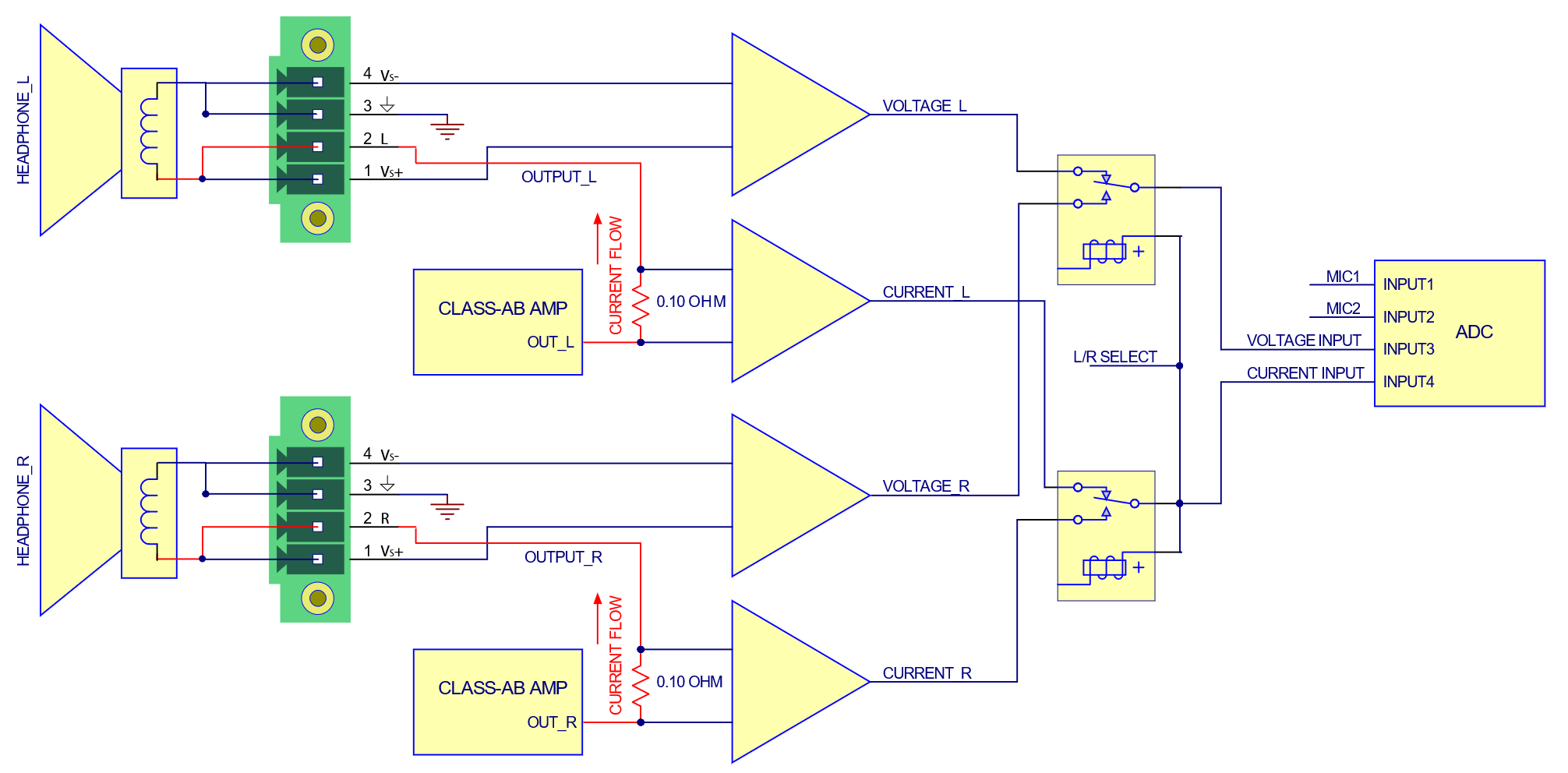 *Figure 11: AIO-H module block diagram*
The left or right channel is selected via the AIO control panel. There are no external connections to these current sense resistors or circuits.
## Amplifier Outputs
Amplified (class D) outputs with Euroblock connectors are provided for driving speakers or other devices. The outputs are single ended with (+) and (-) connections. Both outputs are biased at \~7.5V.
**Important:** Amplifier outputs are floating and not ground-referenced. Connecting a speaker or other low-impedance path from one of the outputs to ground will cause the amplifier to shut down. The amplifier will reset and resume normal operation after the fault is removed.
### Voltage Monitor on Input 3 (VMON)
Voltage measured directly at the speaker terminals is monitored on input 3 of the AIO-S module using two separate wires connected from the speaker terminals to the (V+) and (V-) terminals.
By connecting directly at the speakers, the voltage drop across the speaker wires does not affect the measurement.
### Current Monitor on Input 4 (IMON)
A precision 0.1 Ω current sense resistor is placed in series with the + side of the SPKR output for current monitoring and impedance calculation.
The voltage across the sense resistor is monitored on input 4 of the AIO-S module. There are no external connections to this current sense resistor or circuit.
*Figure 11: AIO-H module block diagram*
The left or right channel is selected via the AIO control panel. There are no external connections to these current sense resistors or circuits.
## Amplifier Outputs
Amplified (class D) outputs with Euroblock connectors are provided for driving speakers or other devices. The outputs are single ended with (+) and (-) connections. Both outputs are biased at \~7.5V.
**Important:** Amplifier outputs are floating and not ground-referenced. Connecting a speaker or other low-impedance path from one of the outputs to ground will cause the amplifier to shut down. The amplifier will reset and resume normal operation after the fault is removed.
### Voltage Monitor on Input 3 (VMON)
Voltage measured directly at the speaker terminals is monitored on input 3 of the AIO-S module using two separate wires connected from the speaker terminals to the (V+) and (V-) terminals.
By connecting directly at the speakers, the voltage drop across the speaker wires does not affect the measurement.
### Current Monitor on Input 4 (IMON)
A precision 0.1 Ω current sense resistor is placed in series with the + side of the SPKR output for current monitoring and impedance calculation.
The voltage across the sense resistor is monitored on input 4 of the AIO-S module. There are no external connections to this current sense resistor or circuit.
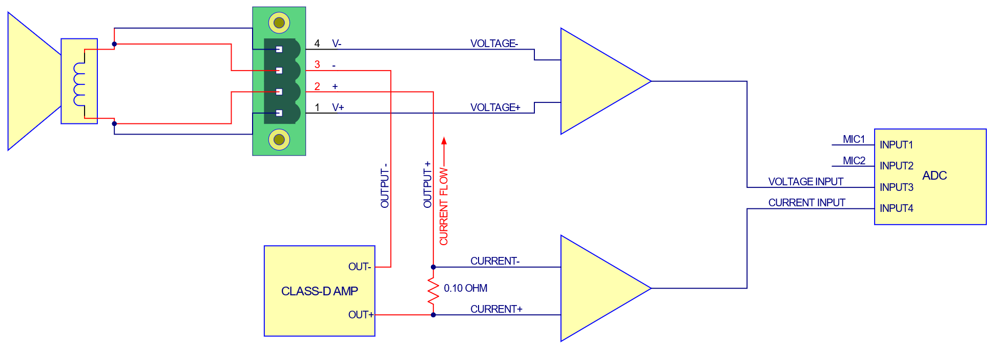 *Figure 12: AIO-S module SPKR block diagram*
# 6. Digital IO
## TDM
The AIO-T module provides up to 10 digital I/O channels through a TDM (Time-Division Multiplexed) interface, for connection directly to audio converters or other ICs.
### Operating Modes
**MASTER mode:** Connectors configured as:
* Four outputs: MCLK, SCLK, SYNC, OUT
* One input: IN
**SLAVE mode:** Connectors configured as:
* Two outputs: MCLK, OUT
* Three inputs: IN, SCLK, SYNC
### Connectors
* **MCLK:** 24.576 MHz master clock output
* **SCLK:** Bit clock output (MASTER) or input (SLAVE). Polarity and bits per frame are programmable. SCLK may also be set to be disabled, outputting a constant “0” logic level.
* **SYNC:** Frame synchronization output (MASTER) or input (SLAVE). SYNC is used to signal the start of an audio frame. Width, polarity, and phase relationship to the audio data are programmable in the control panel.
* **OUT:** Data output, up to 10 channels of 24-bit audio
* **IN:** Data input, up to 10 channels of 24-bit audio
### Logic Levels
I/O logic levels can be set to either 1.8V or 3.3V via the control panel, command line interface, or APIs.
### Termination
* Outputs: High-drive capable with 50 Ω series resistance
* Inputs: 10K Ω input impedance
### Configuration
| Setting | Description |
| ---------------------------------- | -----------------------------------------------------------------------------------------------------------------------------------------------------: |
| **Clock direction** | Clock sink mode: MCLK, SCLK, and SYNC are inputs
*Figure 12: AIO-S module SPKR block diagram*
# 6. Digital IO
## TDM
The AIO-T module provides up to 10 digital I/O channels through a TDM (Time-Division Multiplexed) interface, for connection directly to audio converters or other ICs.
### Operating Modes
**MASTER mode:** Connectors configured as:
* Four outputs: MCLK, SCLK, SYNC, OUT
* One input: IN
**SLAVE mode:** Connectors configured as:
* Two outputs: MCLK, OUT
* Three inputs: IN, SCLK, SYNC
### Connectors
* **MCLK:** 24.576 MHz master clock output
* **SCLK:** Bit clock output (MASTER) or input (SLAVE). Polarity and bits per frame are programmable. SCLK may also be set to be disabled, outputting a constant “0” logic level.
* **SYNC:** Frame synchronization output (MASTER) or input (SLAVE). SYNC is used to signal the start of an audio frame. Width, polarity, and phase relationship to the audio data are programmable in the control panel.
* **OUT:** Data output, up to 10 channels of 24-bit audio
* **IN:** Data input, up to 10 channels of 24-bit audio
### Logic Levels
I/O logic levels can be set to either 1.8V or 3.3V via the control panel, command line interface, or APIs.
### Termination
* Outputs: High-drive capable with 50 Ω series resistance
* Inputs: 10K Ω input impedance
### Configuration
| Setting | Description |
| ---------------------------------- | -----------------------------------------------------------------------------------------------------------------------------------------------------: |
| **Clock direction** | Clock sink mode: MCLK, SCLK, and SYNC are inputs
Clock source mode: MCLK, SCLK, and SYNC are outputs |
| **Bits per frame / bits per word** | 256 bits/frame, 24 bits/word: 10 channels
256 bits/frame, 32 bits/word: 8 channels
128 bits/frame: 4 channels
64 bits/frame: 2 channels |
| **Invert SCLK** | Not inverted: Data and FSYNC clock out on falling edge
Inverted: Data and FSYNC clock out on rising edge |
| **Advance output** | Disabled: Audio output aligned with audio input
Enabled: Audio output advanced specified bits before input |
| **Delay FSYNC and INPUT** | Delays FSYNC and audio input sampling by ½ bit |
| **FSYNC position** | Sets position of positive portion of FSYNC relative to start of frame |
| **FSYNC width** | Sets the width of FSYNC in bits |
# 7. Control Panel
## Overview
The control panel controls and monitors the following AIO hardware functions:
* Analog input and output gain
* Constant-current power to microphones
* TEDS data
* Level meters
* Firmware update
* WASAPI and ASIO driver settings
* Clock source and status
* Diagnostic logging and directory
The control panel is for AIO hardware control only. It does not perform any audio analysis.
## Channels Tab
The Channels tab shows the input and output channels of the connected AIO test system.
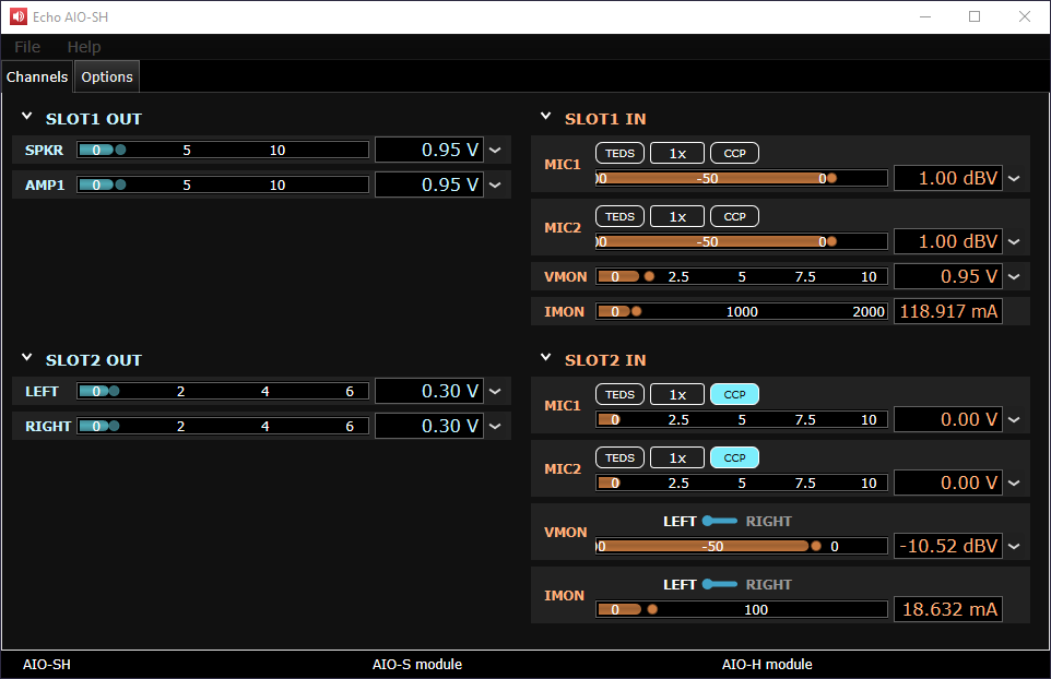 *Figure 15: Channels tab (AIO-SH)*
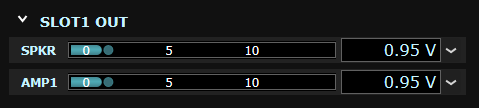
### Outputs
* Level display: Horizontal bar graph and numerical display
* Units selection: dBFS, dBV, Vrms, etc.
* Module-specific controls and indicators
*Figure 15: Channels tab (AIO-SH)*
### Outputs
* Level display: Horizontal bar graph and numerical display
* Units selection: dBFS, dBV, Vrms, etc.
* Module-specific controls and indicators
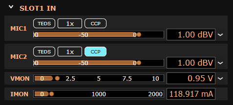
 ### Inputs
* Level display: Horizontal bar graph and numerical display
* **TEDS:** Displays TEDS information from attached microphones
* **Gain:** Sets gain to 1x, 10x, or 100x
* **CCP:** Enables constant current supply for prepolarized microphones
### Inputs
* Level display: Horizontal bar graph and numerical display
* **TEDS:** Displays TEDS information from attached microphones
* **Gain:** Sets gain to 1x, 10x, or 100x
* **CCP:** Enables constant current supply for prepolarized microphones
 ### TEDS Data Window
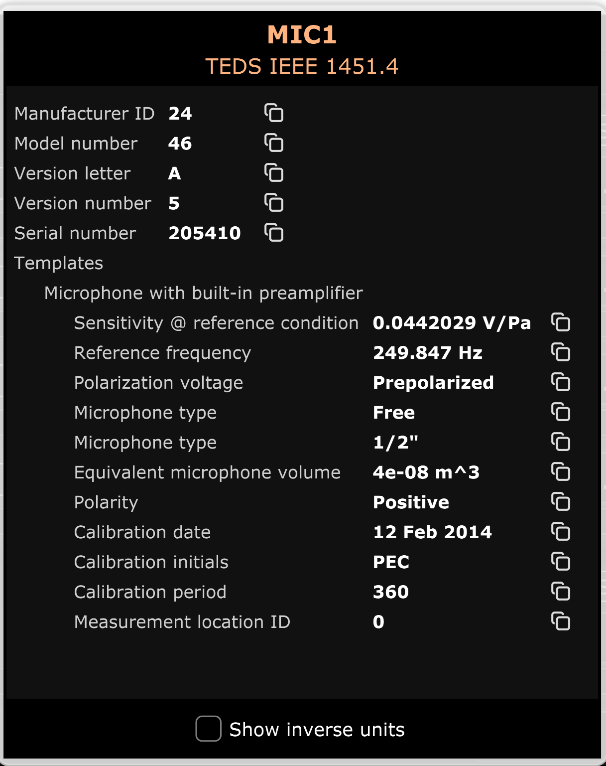 *Figure 16: TEDS data window*
TEDS data is not automatically transferred to the audio analysis software—it must be copied and pasted or manually entered. Data may be easily copied by clicking the icon to the right of each line.
## TDM Tab
The TDM tab is displayed if the AIO test system has an AIO-T module installed.
*Figure 16: TEDS data window*
TEDS data is not automatically transferred to the audio analysis software—it must be copied and pasted or manually entered. Data may be easily copied by clicking the icon to the right of each line.
## TDM Tab
The TDM tab is displayed if the AIO test system has an AIO-T module installed.
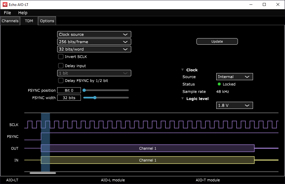 *Figure 17: TDM tab*
### DC Power Supply
* **DC 5V power:** Enable/disable fixed 5V output
* **Variable DC power:** Enable/disable variable output
* **Target voltage:** Set desired output voltage
* **Measured voltage/current:** Display actual output values
* **Current range:** Set measurement range
* **Overcurrent threshold:** Set protection limit
### Aux Control
* **AUX In:** Indicators showing state of Aux In ports
* **AUX Out:** Controls to set Aux Out ports to True or False
### PTH
Pressure, temperature, and humidity data readouts from attached PTH sensor (optional).
## Options Tab
Contains information about the connected AIO test system and configuration options.
*Figure 17: TDM tab*
### DC Power Supply
* **DC 5V power:** Enable/disable fixed 5V output
* **Variable DC power:** Enable/disable variable output
* **Target voltage:** Set desired output voltage
* **Measured voltage/current:** Display actual output values
* **Current range:** Set measurement range
* **Overcurrent threshold:** Set protection limit
### Aux Control
* **AUX In:** Indicators showing state of Aux In ports
* **AUX Out:** Controls to set Aux Out ports to True or False
### PTH
Pressure, temperature, and humidity data readouts from attached PTH sensor (optional).
## Options Tab
Contains information about the connected AIO test system and configuration options.
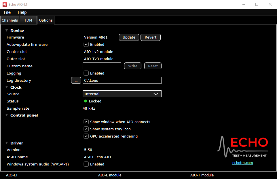 *Figure 19: Options tab*
### Device
* **Firmware:** Current version and update options
* **Auto-update firmware:** Automatic update prompts
* **Custom name:** Set unique USB device name
* **Logging:** Enable diagnostic logging
### Clock
* **Source:** Internal, USB, or TDM
* **Status:** Clock lock indicator
* **Sample rate:** ASIO clock rate
### Control Panel
* **Show window when AIO connects:** Auto-display on connection
* **Show system tray icon:** System tray visibility
* **GPU accelerated rendering:** Hardware acceleration for meters
### Driver
* **Version:** Installed driver version
* **ASIO name:** Driver name in measurement software
* **Windows system audio (WASAPI):** Enable WASAPI support
## File Menu
*Figure 19: Options tab*
### Device
* **Firmware:** Current version and update options
* **Auto-update firmware:** Automatic update prompts
* **Custom name:** Set unique USB device name
* **Logging:** Enable diagnostic logging
### Clock
* **Source:** Internal, USB, or TDM
* **Status:** Clock lock indicator
* **Sample rate:** ASIO clock rate
### Control Panel
* **Show window when AIO connects:** Auto-display on connection
* **Show system tray icon:** System tray visibility
* **GPU accelerated rendering:** Hardware acceleration for meters
### Driver
* **Version:** Installed driver version
* **ASIO name:** Driver name in measurement software
* **Windows system audio (WASAPI):** Enable WASAPI support
## File Menu
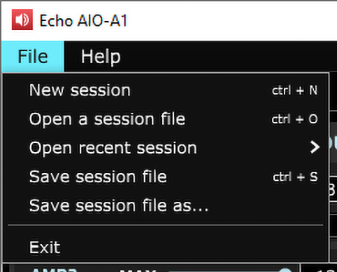 *Figure 20: File menu*
Allows you to open and save sessions. An AIO session stores all current hardware settings in a text file that can be used to reset the hardware to a previous state.
## Help Menu
Contains version information and build date of the currently installed control panel application.
*Figure 20: File menu*
Allows you to open and save sessions. An AIO session stores all current hardware settings in a text file that can be used to reset the hardware to a previous state.
## Help Menu
Contains version information and build date of the currently installed control panel application.
 *Figure 21: AIO About window*
# 8. Programmatic Control
## Command-line Application
The command-line application is primarily used for configuring an AIO test system from another application. This is especially useful for automating AIO setup as part of your test sequence.
* **Windows:** Installed with the Echo AIO Driver
* **macOS:** Copy command-line application and EchoAIOInterface.dylib library to a folder
Download the complete AIO Command-line Reference documentation
## API
AIO includes a C library dll which makes it possible to control the AIO test system from your own code.
Visit the Echo AIO API Example GitHub repository
# 9. Specifications
## Data
### Microphone / Line Inputs
| Parameter | Specification |
| --------------------------------- | ---------------------------------------------------------------------------------------------------------------- |
| Input impedance | 1 MΩ |
| Input coupling | AC |
| Input gain | 1x, 10x, and 100x |
| Voltage, full scale (1x gain) | 8.75 Vpk (+15.8 dBV) |
| Voltage, maximum | ±15 Vpk |
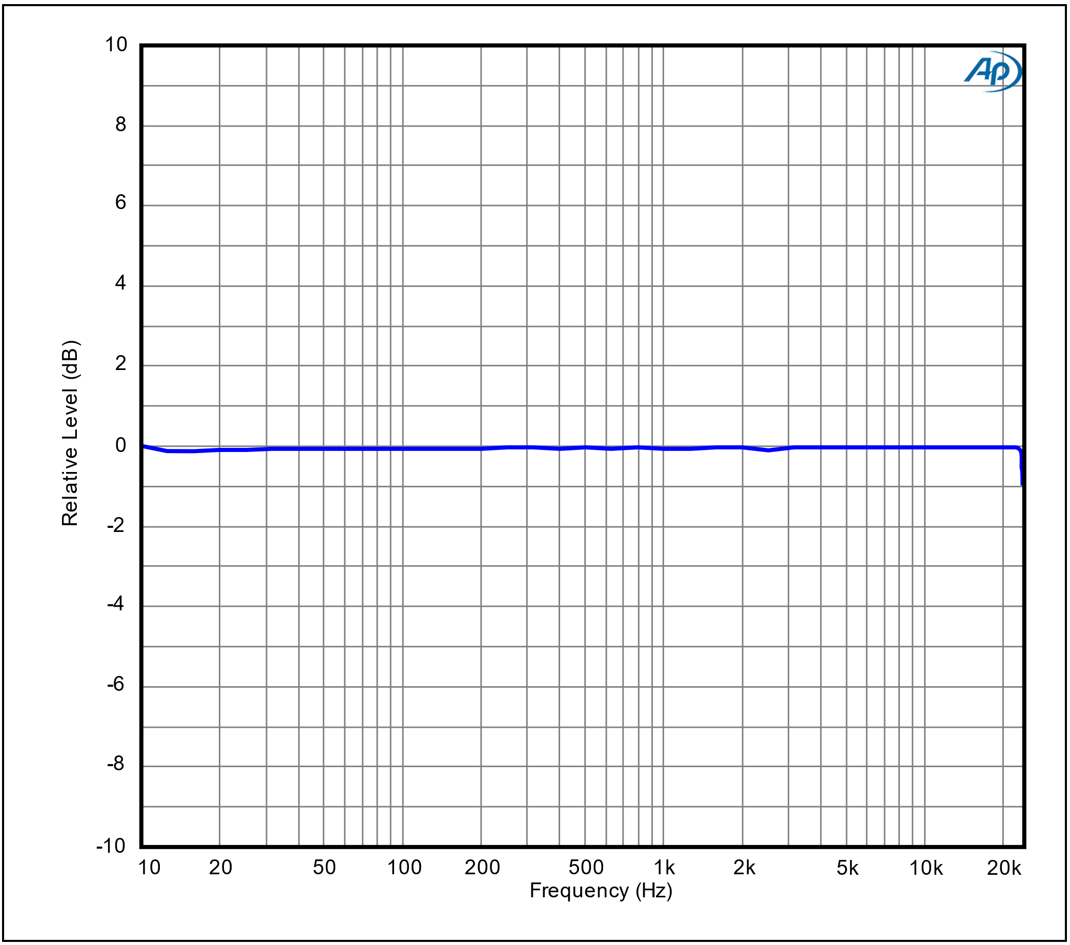
| Frequency response | ±0.01 dB (10 Hz – 22 kHz) @ 48k SR
*Figure 21: AIO About window*
# 8. Programmatic Control
## Command-line Application
The command-line application is primarily used for configuring an AIO test system from another application. This is especially useful for automating AIO setup as part of your test sequence.
* **Windows:** Installed with the Echo AIO Driver
* **macOS:** Copy command-line application and EchoAIOInterface.dylib library to a folder
Download the complete AIO Command-line Reference documentation
## API
AIO includes a C library dll which makes it possible to control the AIO test system from your own code.
Visit the Echo AIO API Example GitHub repository
# 9. Specifications
## Data
### Microphone / Line Inputs
| Parameter | Specification |
| --------------------------------- | ---------------------------------------------------------------------------------------------------------------- |
| Input impedance | 1 MΩ |
| Input coupling | AC |
| Input gain | 1x, 10x, and 100x |
| Voltage, full scale (1x gain) | 8.75 Vpk (+15.8 dBV) |
| Voltage, maximum | ±15 Vpk |
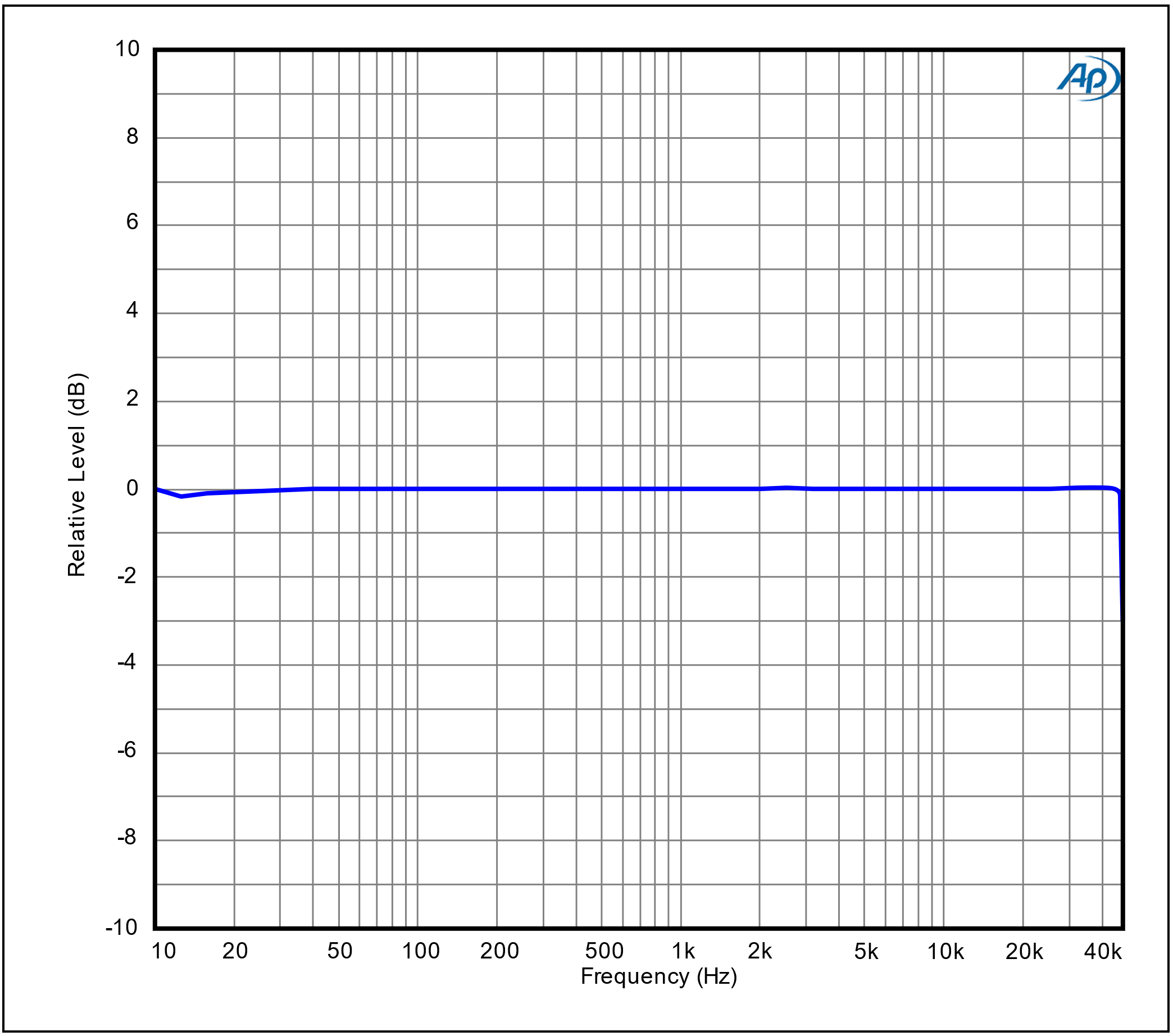
| Frequency response | ±0.01 dB (10 Hz – 22 kHz) @ 48k SR
±0.01 dB (10 Hz – 44 kHz) @ 96k SR
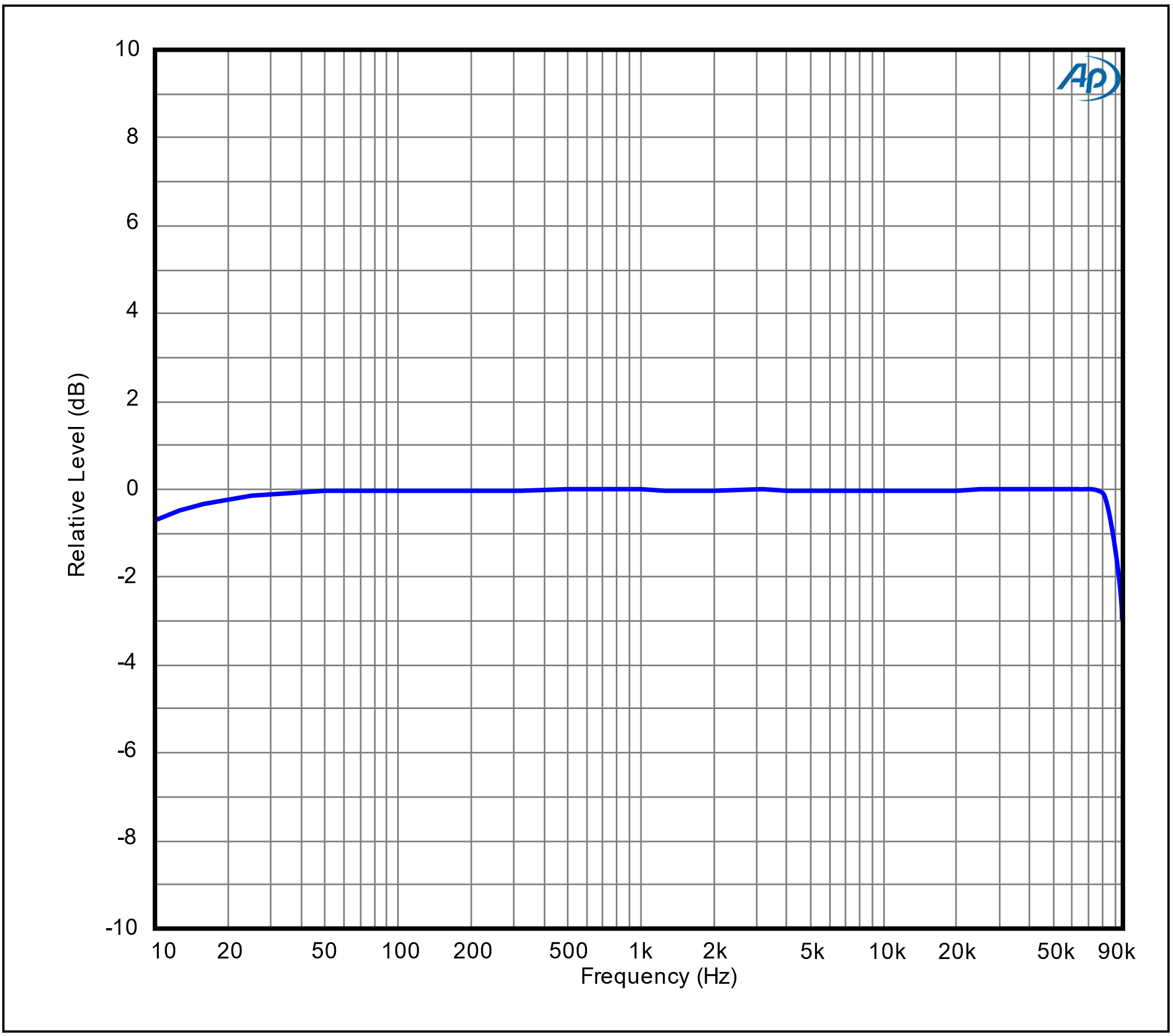
±1 dB (10 Hz – 86 kHz) @ 192k SR |
| Input bandwidth (-3 dB @ 192k SR) | 94 kHz |
| Dynamic range (20 kHz BW) | 112 dB |
| THD+N (1x gain, 20 kHz BW) | \< -105 dB (20 Hz – 20 kHz) |
| Noise, residual | 17 µV |
| IMD (SMPTE 4:1 @ full scale) | -95 dB |
| Crosstalk | \< -122 dB (20 Hz – 20 kHz) |
| Phase error | \< ±0.1° @ 20 kHz |
| Constant current supply | CCP/IEPE/ICP, 4 mA |
| TEDS reader | IEEE 1451.4 Class 1 |
### Line Outputs
| Parameter | Specification |
| ---------------------------------- | ---------------------------------------------------------------------------------------------------------------- |
| Output impedance | 102 Ω |
| Output coupling | DC |
| Minimum load | 600 Ω |
| Voltage, maximum | 16 Vrms (+24 dBV) balanced
8 Vrms (+18 dBV) unbalanced |
| DC offset, range | ±22.6 VDC (bal); ±11.3 VDC (unbal) |
| DC offset, residual | \< ±1.6 mV |
| Frequency response | ±0.01 dB (10 Hz – 21 kHz) @ 48k SR
±0.01 dB (10 Hz – 43 kHz) @ 96k SR
±1 dB (10 Hz – 75 kHz) @ 192k SR |
| Output bandwidth (-3 dB @ 192k SR) | 90 kHz |
| Dynamic range (20 kHz BW) | 120 dB |
| THD+N (20 kHz BW) | \< -102 dB (20 Hz – 20 kHz) |
| Noise, residual | 17 µV (bal), 8.5 µV (unbal) |
| IMD (SMPTE 4:1 @ full scale) | -101 dB |
| Crosstalk | \< -122 dB (20 Hz – 20 kHz) |
| Phase error | \< ±0.1° @ 20 kHz |
### Headphone Outputs
| Parameter | Specification |
| ---------------------------------- | ---------------------------------------------------------------------------------------------------------------- |
| Output impedance | 350 mΩ |
| Output coupling | DC |
| Load, minimum | 16 Ω |
| Voltage, maximum | 3 Vrms (+9.5 dBV) (≥ 32 Ω load) |
| Current, maximum | 125 mA |
| DC offset, range | ±4.24 VDC (≥ 32 Ω load)
±2.8 VDC (16 Ω load) |
| DC offset, residual | \< ±6 mV |
| Power output (20 Hz – 20 kHz) | 281 mW @ \< 0.0016% THD+N (32 Ω)
250 mW @ \< 0.0019% THD+N (16 Ω) |
| Frequency response | ±0.01 dB (10 Hz – 21 kHz) @ 48k SR
±0.01 dB (10 Hz – 43 kHz) @ 96k SR
±1 dB (10 Hz – 75 kHz) @ 192k SR |
| Output bandwidth (-3 dB @ 192k SR) | 89 kHz |
| Dynamic range (20 kHz BW) | 120 dB |
| Noise, residual | 2.8 µV |
| IMD (SMPTE 4:1) | \< -82 dB (> 375 µW) |
| Crosstalk | \< -119 dB (20 Hz – 20 kHz) |
| Phase error | \< ±0.1° @ 20 kHz |
| Impedance measurement accuracy | ≤ 1% (20 Hz – 20 kHz) |
### Amplifier / Speaker Outputs
| Parameter | Specification |
| ---------------------------------- | ------------------------------------------------------- |
| Output impedance | 190 mΩ (amp), 290 mΩ (spkr) |
| Output coupling | AC |
| Load, minimum | 4 Ω |
| Voltage, full scale | 9.475 Vrms (8 Ω load) |
| DC offset, residual | \< ±6 mV |
| Power output (20 Hz – 20 kHz) | 10 W @ \<0.2% THD+N (8 Ω)
6 W @ \<0.3% THD+N (4 Ω) |
| Frequency response | ±0.2 dB (10 Hz – 20 kHz) (8 Ω load) |
| Output bandwidth (-3 dB @ 192k SR) | 44 kHz |
| Dynamic range (20 kHz BW) | 100 dB |
| Noise, residual | 100 µV |
| IMD (SMPTE 4:1) | \< -53 dB (≥ 0.5 mW) |
| Crosstalk | \< -70 dB (20 Hz – 20 kHz) |
| Phase error | \< ±1.2° @ 20 kHz |
| Impedance measurement accuracy | ≤ 0.5% (20 Hz – 20 kHz) |
### TDM
| Parameter | Specification |
| ------------------- | -------------------- |
| Channels | 2, 4, 8, or 10 |
| Clock source | Internal or external |
| Bits per frame | 64, 128, or 256 |
| Bits per sample | 24 or 32 |
| Frame sync width | 1 – 128 bits |
| Frame sync position | Bit 0 – 255 |
| Sample rate | 44.1k, 48k |
### GPIO
| Parameter | Specification |
| ------------------ | ---------------------- |
| Inputs and outputs | 8/8 |
| Input level | TTL |
| Output type | Open drain, 250 mA max |
### Environmental Sensor (PTH)
| Parameter | Specification |
| -------------------- | ------------------------ |
| Atmospheric pressure | 260 to 1260 hPa absolute |
| Ambient temperature | -40 °C – 90 °C ±0.2° |
| Humidity | ±1.5 % relative humidity |
### DC Power
| Parameter | Specification |
| ------------------------------------- | -------------------------------------------------- |
| Fixed DC power supply | 5 VDC, 1 A max |
| Battery simulator, output | 600mVDC – 5 VDC, 1 A max, with current measurement |
| Battery simulator, setting resolution | 1 mV |
### General
| Parameter | Specification |
| ---------- | -------------------------------------------------- |
| Power | 90 – 264 VAC, 50/60 Hz, 60 W |
| Dimensions | 17.5" (44.4 cm) x 8.75" (22.2 cm) x 1.75" (4.4 cm) |
| Weight | 42.5 lbs (19.3 kg) |
## Graphs
### Frequency Response Graphs
 *Frequency Response (48k SR)*
 *Frequency Response (96k SR)*
 *Frequency Response (192k SR)*
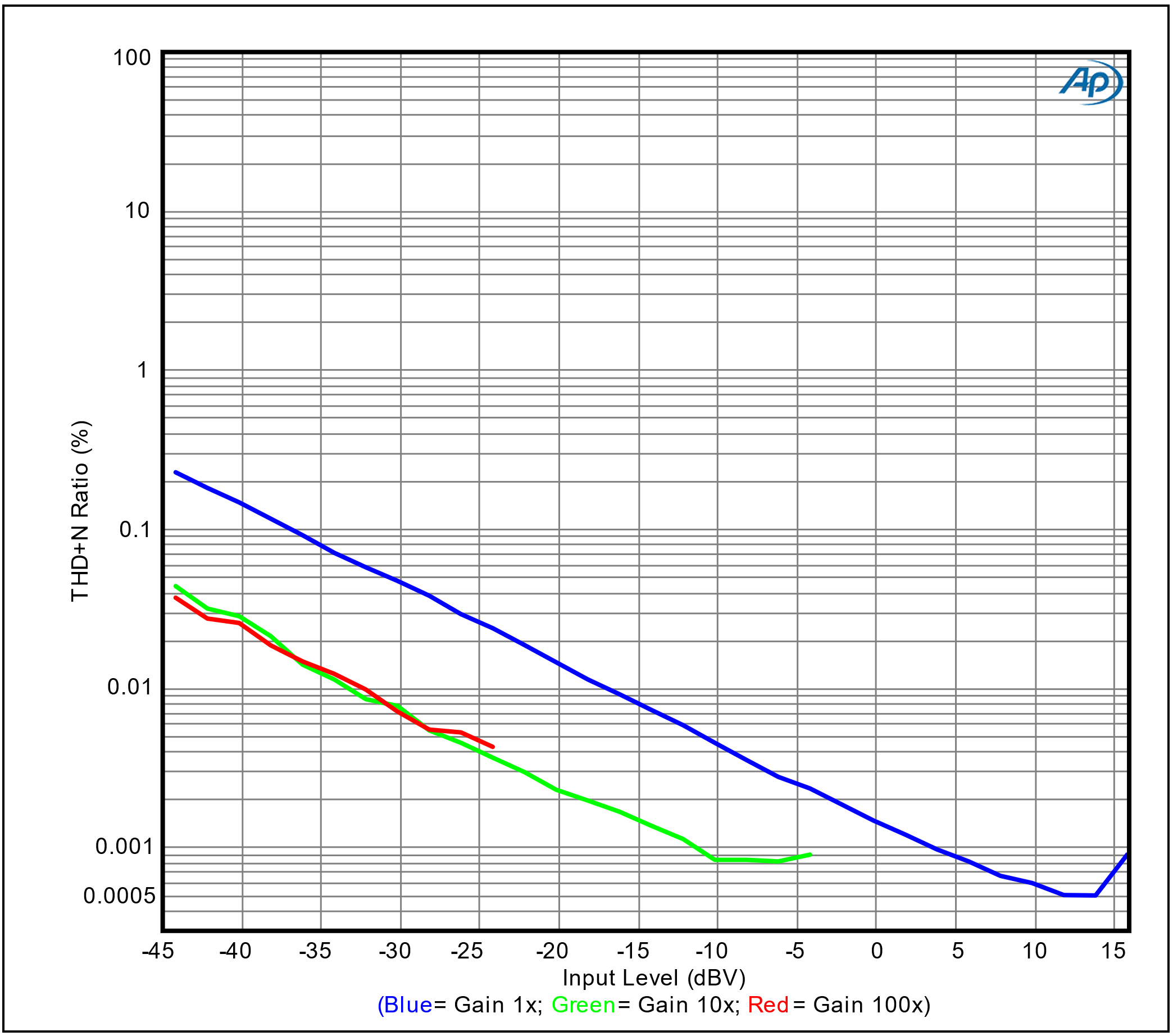 *THD+N Ratio vs Input Level (48k SR)*
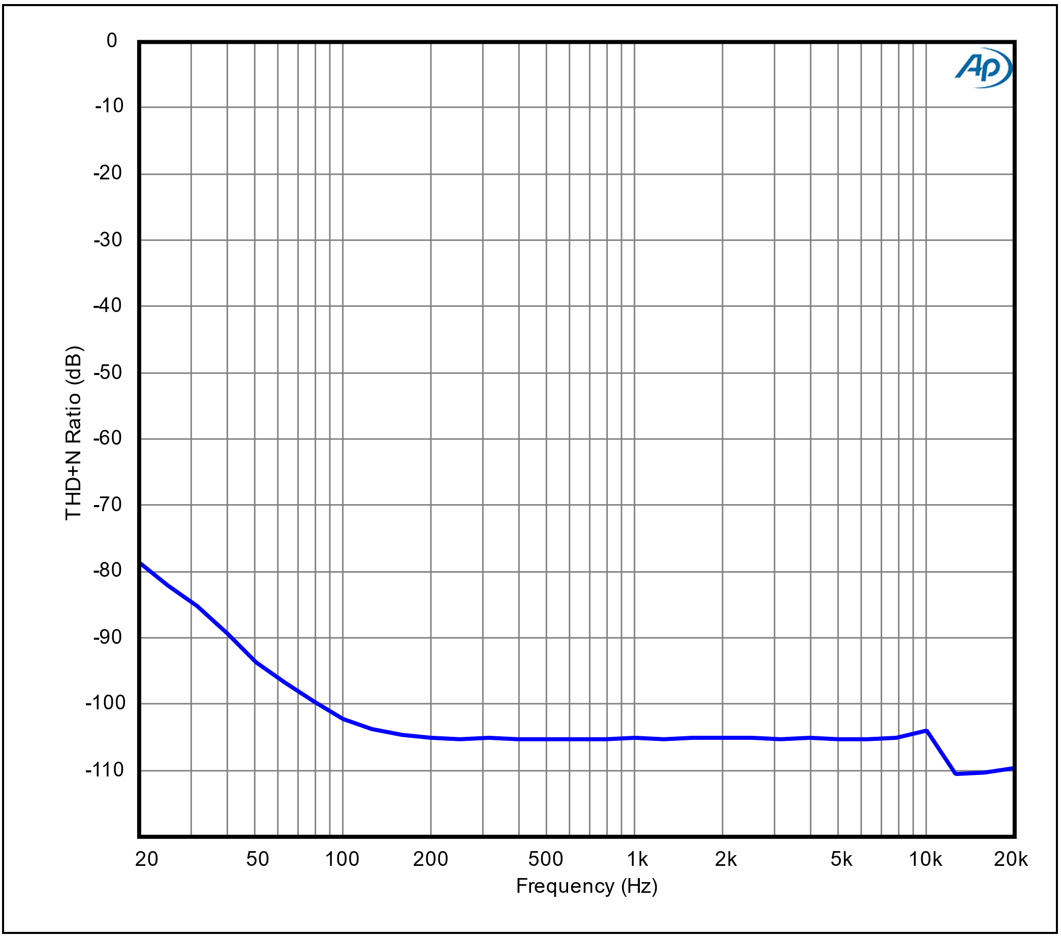 *THD+N Ratio vs Frequency (48k SR)*
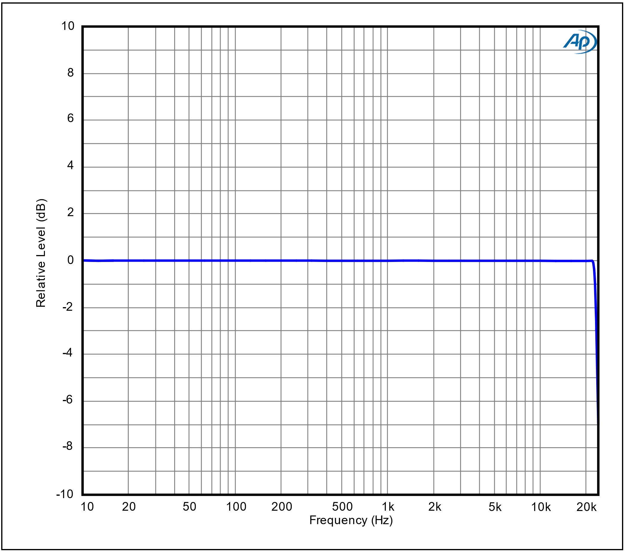 *Frequency Response (48k SR)*
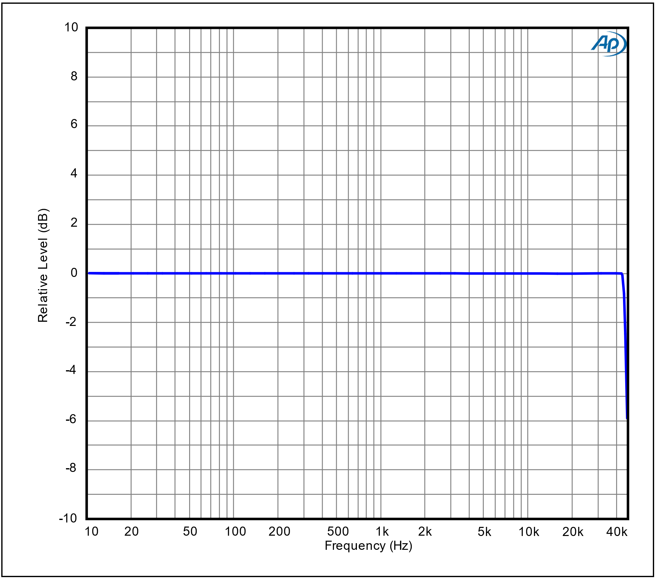 *Frequency Response (96k SR)*
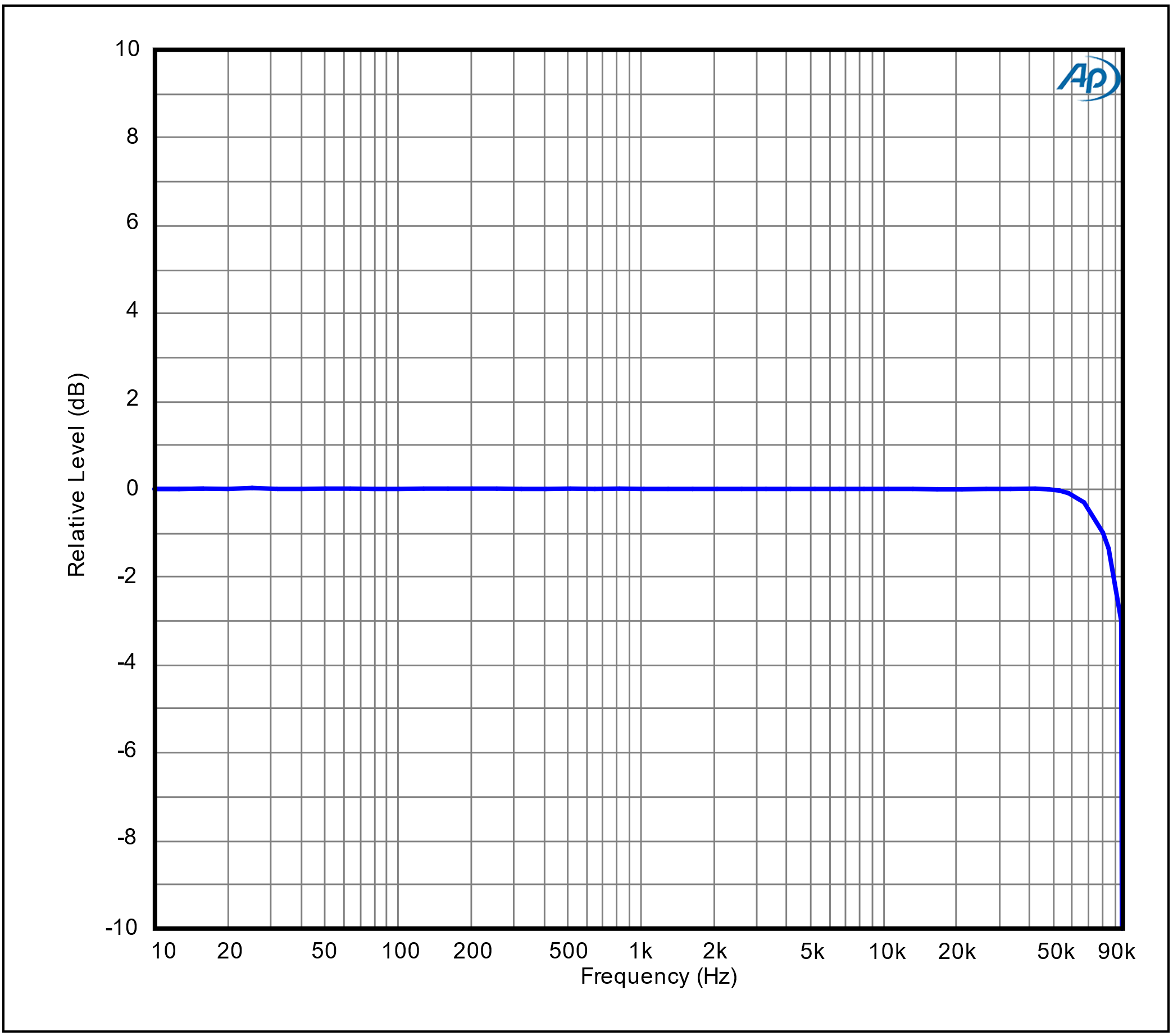 *Frequency Response (192k SR)*
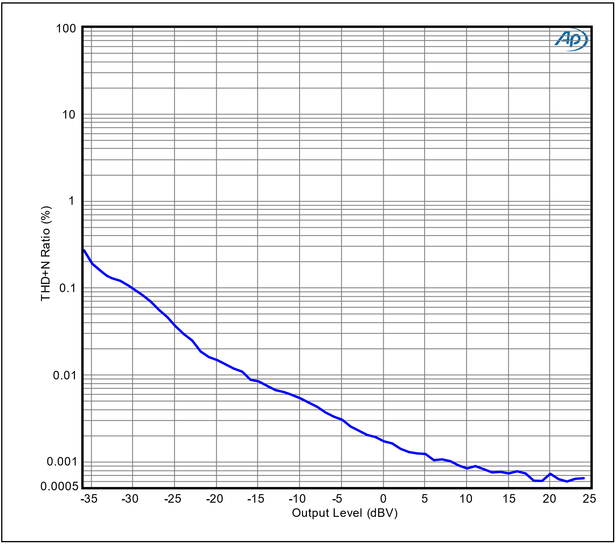 *THD+N Ratio vs Output Level (48k SR)*
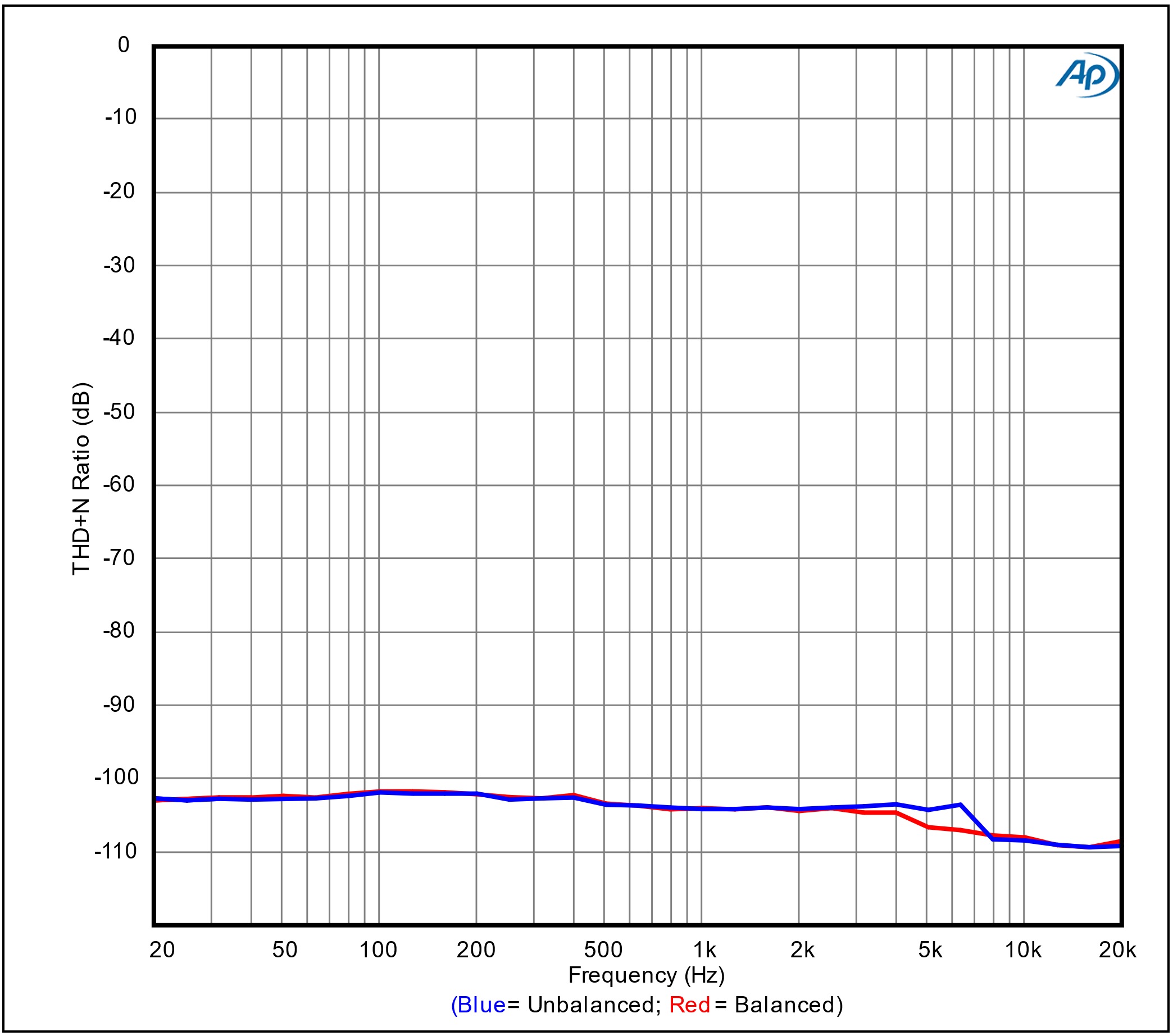 *THD+N Ratio vs Frequency (48k SR)*
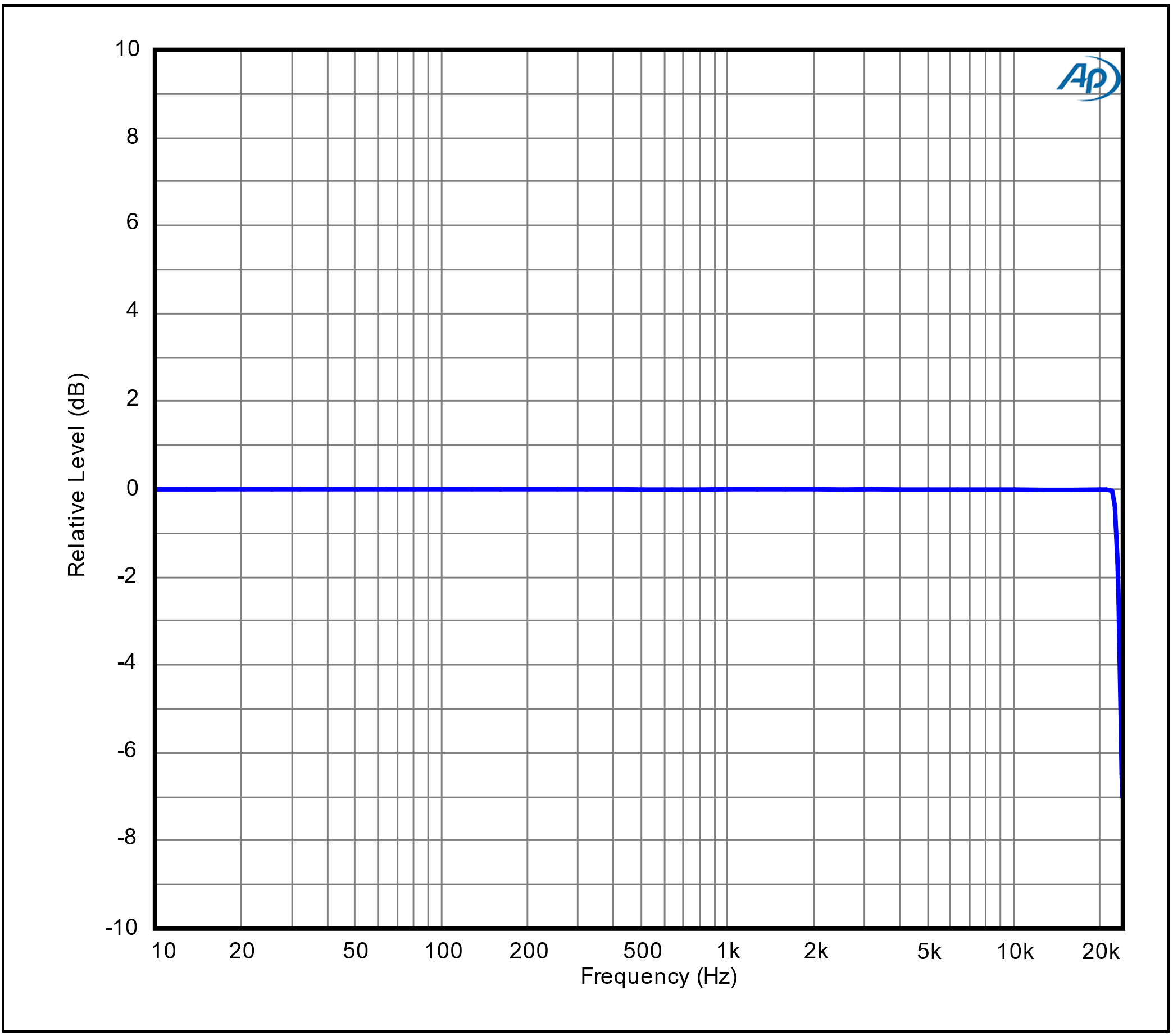 *Frequency Response (48k SR)*
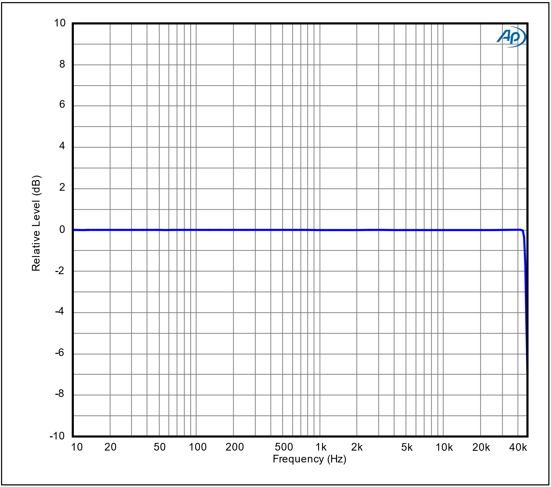 *Frequency Response (96k SR)*
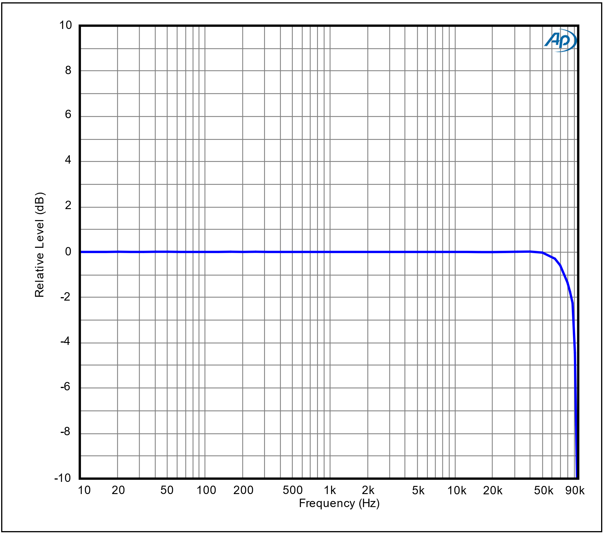 *Frequency Response (192k SR)*
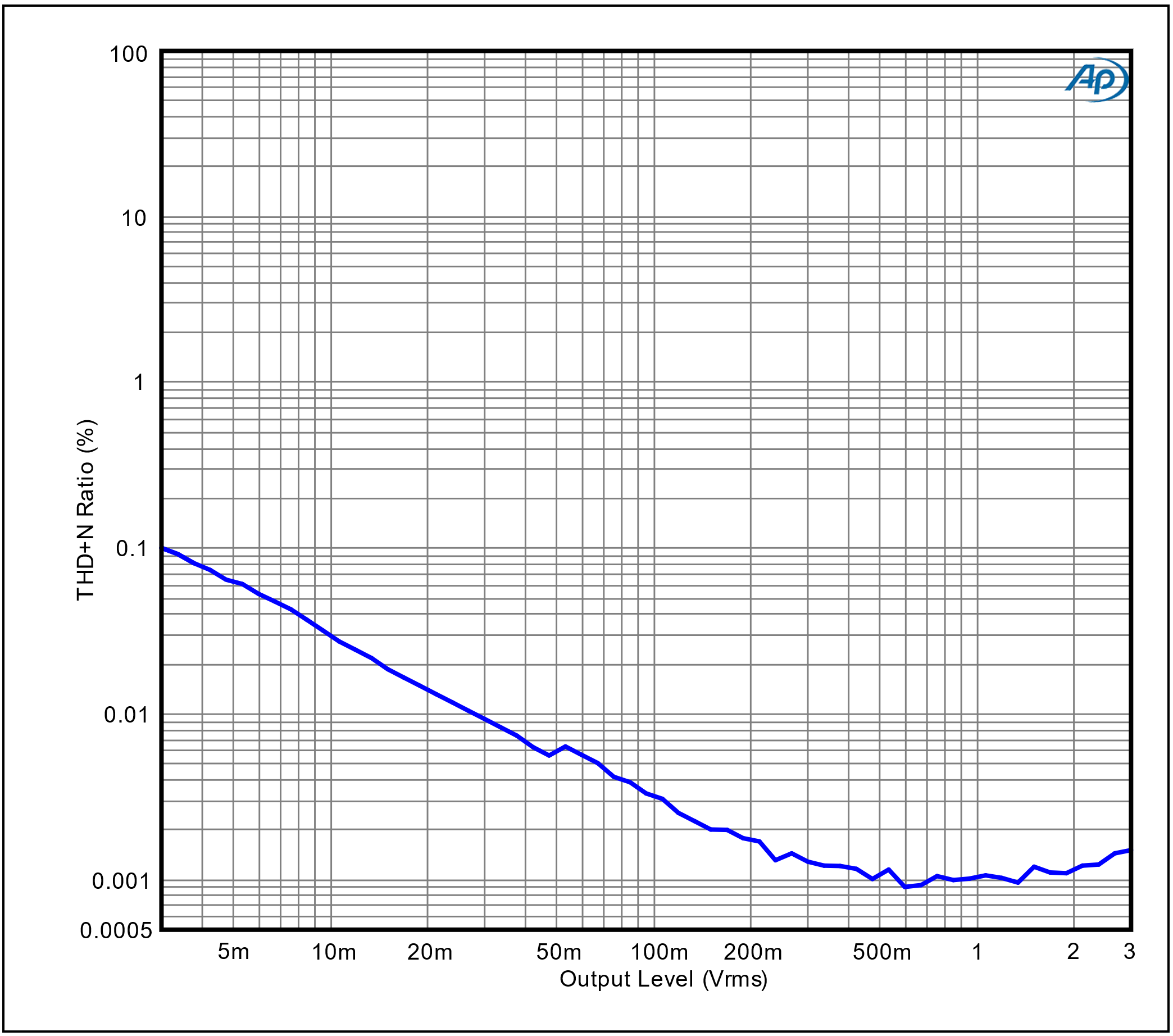 *THD+N Ratio vs Output Level (48k SR)*
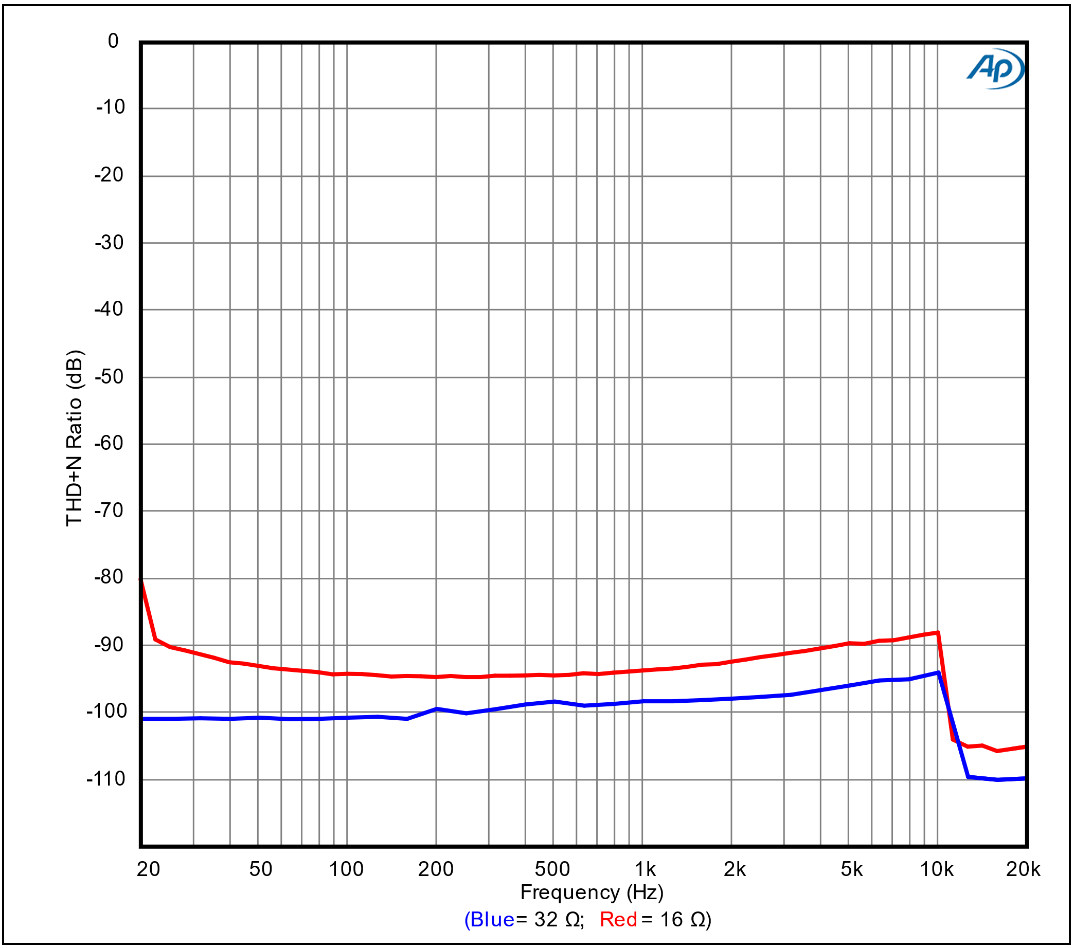 *THD+N Ratio vs Frequency (48k SR)*
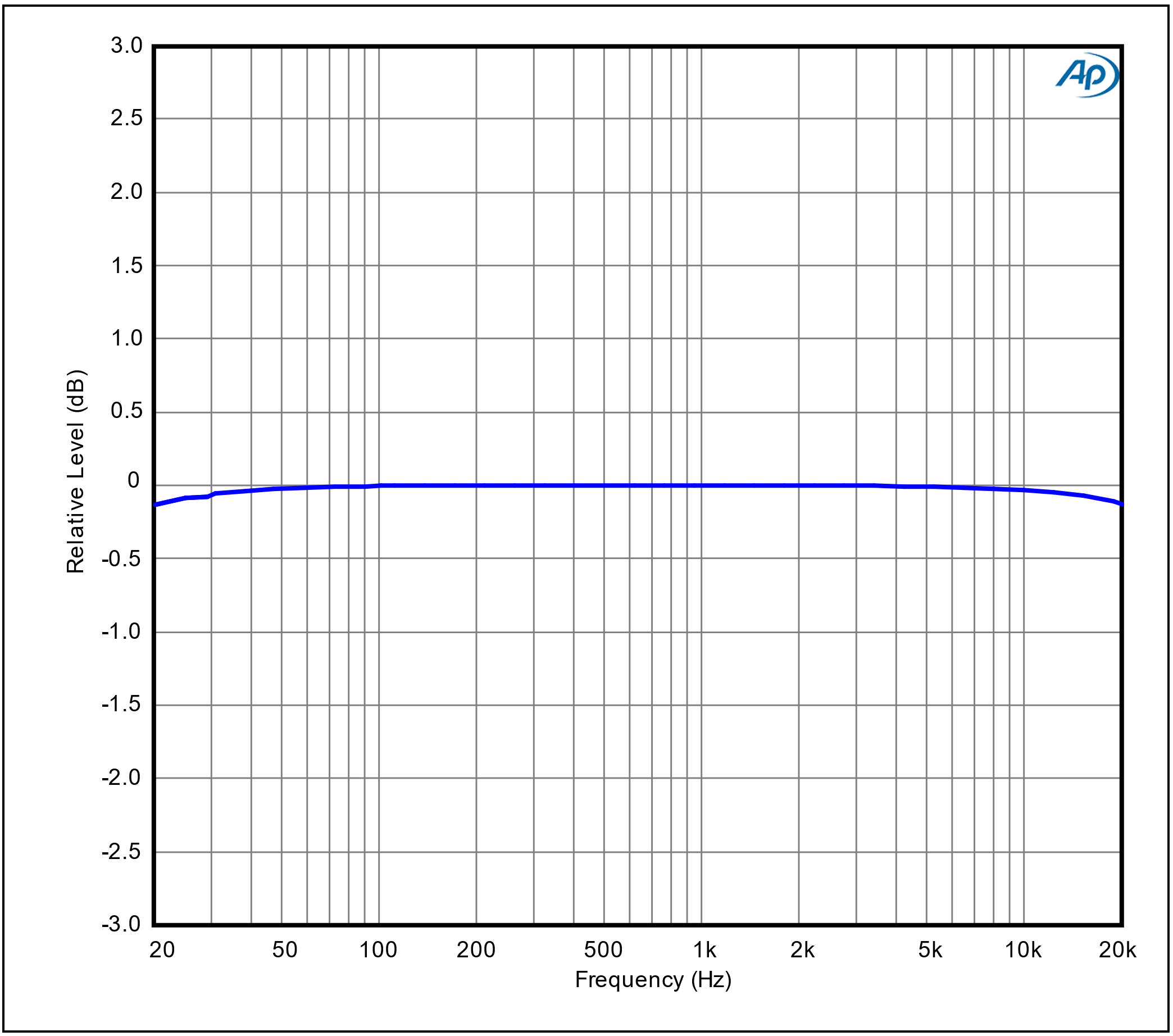 *Frequency Response (48k SR) (8 Ω load)*
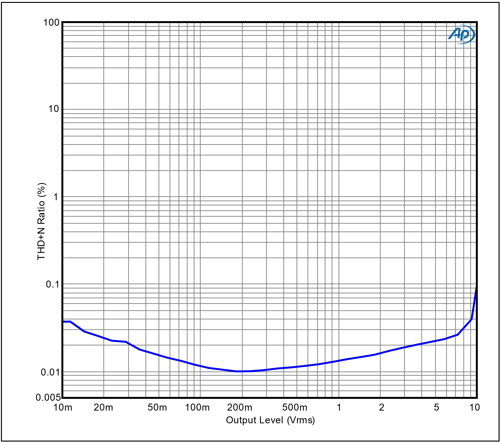 *THD+N Ratio vs Output Level (48k SR) (8 Ω load)*
Contact Echo for info or support.
*THD+N Ratio vs Output Level (48k SR) (8 Ω load)*
Contact Echo for info or support.